Fender Design - Wheel Arch Challenge
FENDER DESIGN-WHEEL ARCH
AIM:
To Calculate the Wheel Arch gap at required points and check whether the car passes the European standard.
THEORY:
The wheel arch is the fender's semicircular arch-shaped cavity where the wheel is located.
To prevent chipping inside the engine compartment and also to pedestrians, the wheels should be positioned so that they are at a specific distance from the outermost edge of the fender.
REQUIREMENTS:
Vehicle regulations are the specifications that vehicles must meet in order to be authorised for sale or use in a specific nation or area. There are numerous s available based on various nationalities. ARAI and SAE are a couple of the regulations that the Indian automotive industry uses.
According to the conditions shown in the illustration below, the distance between the wheel arch and tyre profile must be measured in accordance with European law.
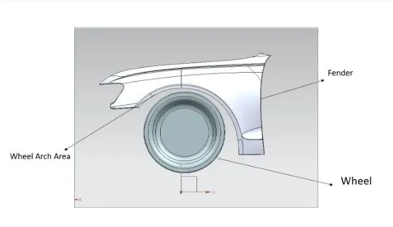
Image 1: Wheel Arc Profile Challenge.
Before moving on lets know what European Regulations, Japanese Regulations and US Regulations in detail with example and after that we can procced further.
European Regulation:
According to European Regulation, there must be more than 10mm of clearance between the fender and the tyre profile. The value is determined by projecting a point 30 degrees forward and 50 degrees backward, respectively. The clearance measured at points a and b in five different tyre positions is satisfactory. However, there is a negative sign at points c, d, and e that indicated the interference of a wheel arch with a tyre.
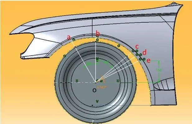
Image 2: European Standard Example Model.
| MEASURED POINTS | a | b | c | d | e |
| REQUIRED LENGTH | 10 | 10 | 10 | 10 | 10 |
| ACTUAL LENGTH | 10 | 9.92 | -6.62 | -10.6 | -14.7 |
| REMARKS | PASS | FAIL | FAIL | FAIL | FAIL |
Table 1: European standard Example Model Table.
Japanese Regulation:
According to Japanese law, there must be more than 5mm of space between the tyre and the fender. The projected sites to be measured are at angles of 30° and 50°, respectively, forward and backward.
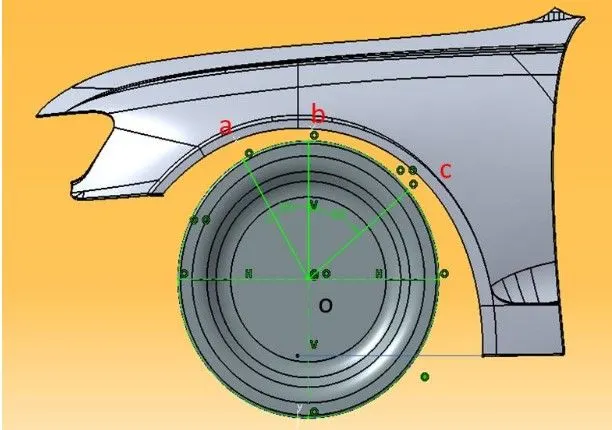
Image 3: Japanese Regulation Model Example.
| MEASURED POINTS | a | b | c |
| REQUIRED LENGTH | 5 | 5 | 5 |
| ACTUAL LENGTH | 10 | 9.92 | -6.69 |
| REMARKS | PASS | PASS | FAIL |
Table 2 Japanese Regulation Model Example Table.
According to Japanese law, there must be more than 5mm of space between the tyre and the fender. The projected sites to be measured are at angles of 30° and 50°, respectively, forward and backward. As a result, at point c, the clearance value is negative, indicating interference, and changes must be made.
US Regulation:
According to US law, there must be more than 5mm of space between the tyre and the fender. The measurement points are projected at angles of 0° forward and 100°, respectively. As a result, 10° are separated into each place. As a result, the anticipated distances are assessed at about 21 distinct locations.
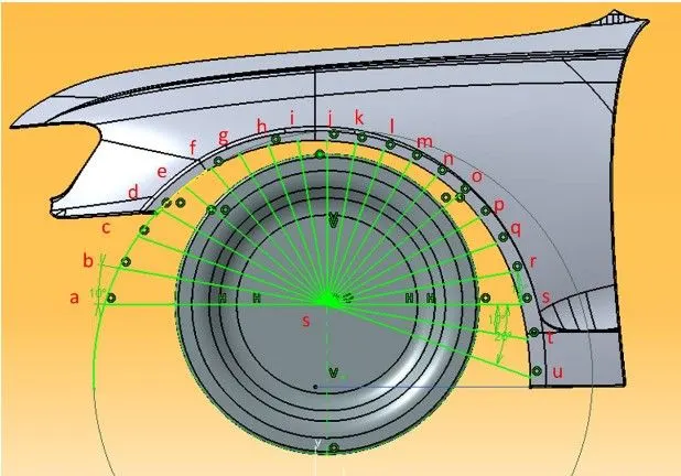
Image 4: US Regulation Example Model.
| MEASURED POINTS | a | b | c | d | e | f | g | h | i | j | k | l | m | n | o | p | q | r | s | t | u |
| REQUIRED LENGTH | 5 | 5 | 5 | 5 | 5 | 5 | 5 | 5 | 5 | 5 | 5 | 5 | 5 | 5 | 5 | 5 | 5 | 5 | 5 | 5 | 5 |
| ACTUAL LENGTH | -67.4 | -28.9 | -4.9 | 5.8 | 9.2 | 10 | 10 | 10 | 10 | 9.9 | 9.4 | 8.2 | 6.2 | 3.5 | 0 | -4.5 | -9.6 | -15.5 | -22.1 | -29.5 | -37.7 |
| REMARKS | FAIL | FAIL | FAIL | PASS | PASS | PASS | PASS | PASS | PASS | PASS | PASS | PASS | PASS | FAIL | FAIL | FAIL | FAIL | FAIL | FAIL | FAIL | FAIL |
Table 3: US Regulation Example Model Table.
According to the data, the clearance value is greater than 5mm at locations between d and m, but it is very low or even negative at a number of sites between a and c and between n and u, indicating that the fender assembly and tyre are interfering. In order to comply with US regulation requirements, design modification must be made at the designated points.
PROCEDURE:
- On the wheel's outermost edge, create a datum plane.
- Create a vertical reference line from the center.
- convert the outermost curve into circle using project curve under sketch box commands.
- same way to fender's outer arc.
- use line command to draw lines. Point command to create points.
- Section A is represented by the vertical centre axis of the wheel.
- Create a line 30 degrees ahead from the axis of the wheel that is long enough to intersect at the wheel's outer edge.
- Section B is represented by this line.
- Create a line 50 degrees back from the axis of the wheel that is long enough to intersect at the wheel's outermost edge.
- Section C is represented by this line.
- At a vertical distance of 150 mm from the wheel's horizontal central axis facing backward, Section E is formed.
Section D is represented by the line that divides sections C and E.
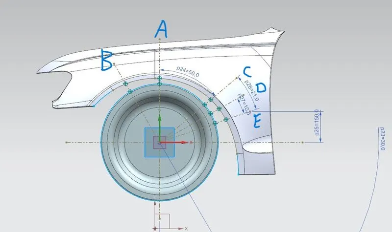
Image 5: Challenge Model.
Point A
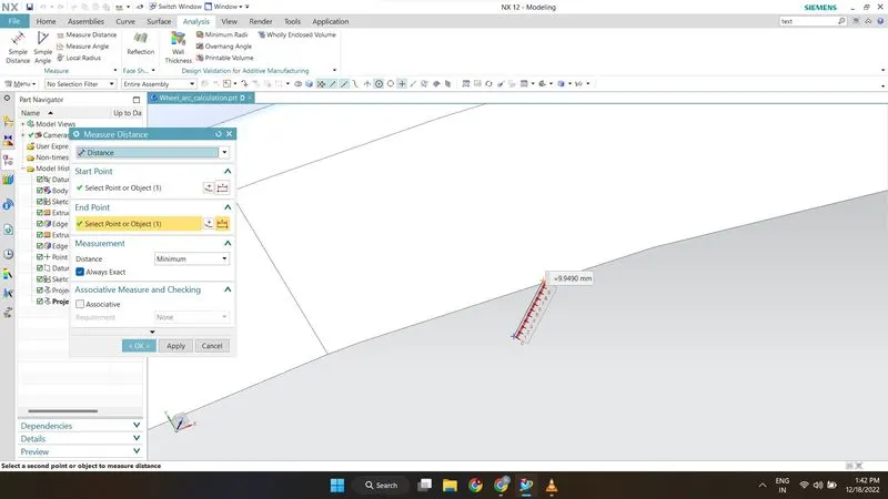
Image 6: Point A.
Point B
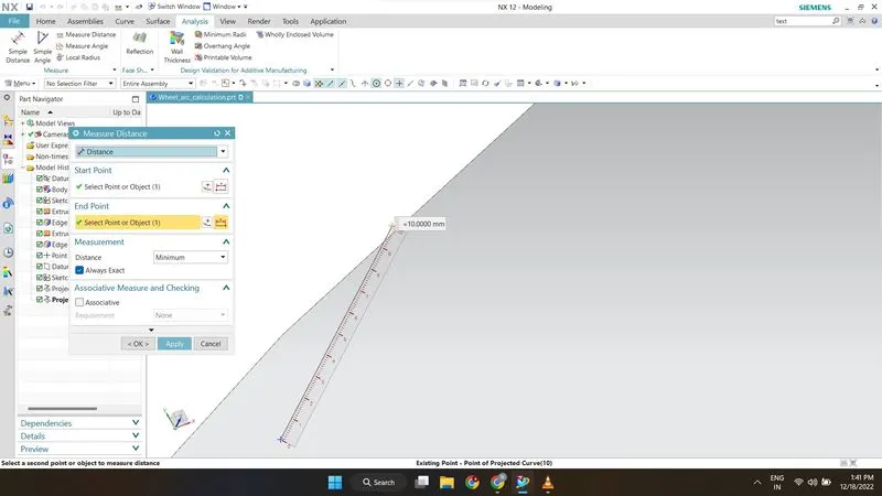
Image 7: Point B.
Point C
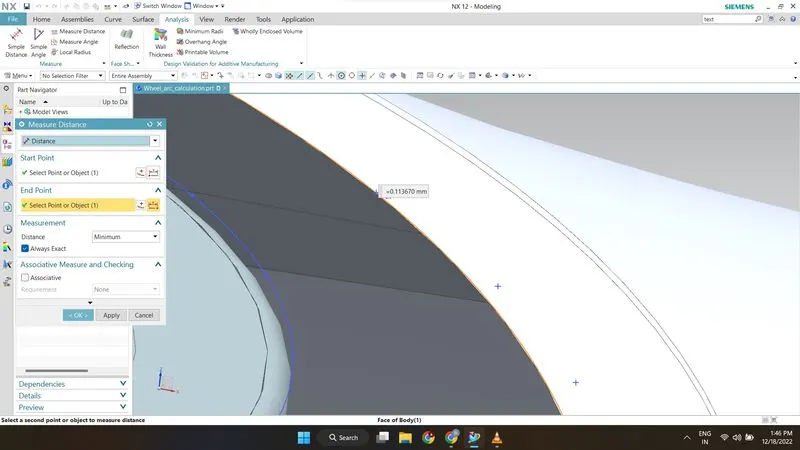
Image 8: Point C.
Point D
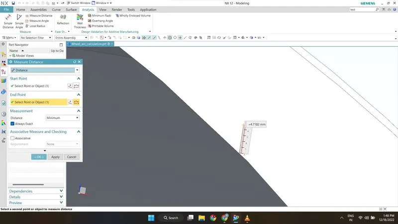
Image 9: Point D.
Point E
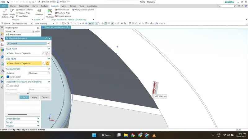
Image 10: Point E.
CALCULATING L&R
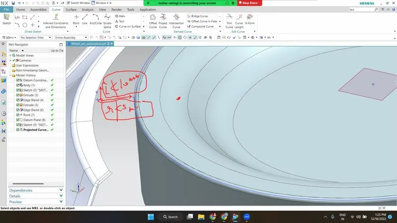
Image 11: Calculating L&R.
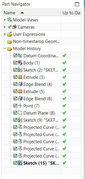
Image 11: Part Navigator.
TABULAR
| MEASURED POINTS | A | B | C | D | E |
| REQUIRED (L) | 10 | 10 | 10 | 10 | 10 |
| ACTUAL (L) | 9.949 | 10.000 | -0.113 | -4.7182 | -10.169 |
| REMARKS | FAIL | PASS | FAIL | FAIL | FAIL |
Table 4: Final Value Table of Challenge Under European Regulations.
CONCLUSION
The model does not meet European standards because it only satisfies the criteria at section B and does not comply with the requirements in any other areas. The fender's curve needs to be modified by the styling team in order to meet the 10 mm criteria.