Fender Design - Wheel Arch Challenge
Objective:
To examine the given fender design to verify if the wheel arch of the fender meets the European Standards
Fender is part of an automobile (vehicle body)that frames a wheel well.
its primary purpose is to to prevent sand,mud,rocks, liquid,and other road spray from being throw into air by the rotating tire.
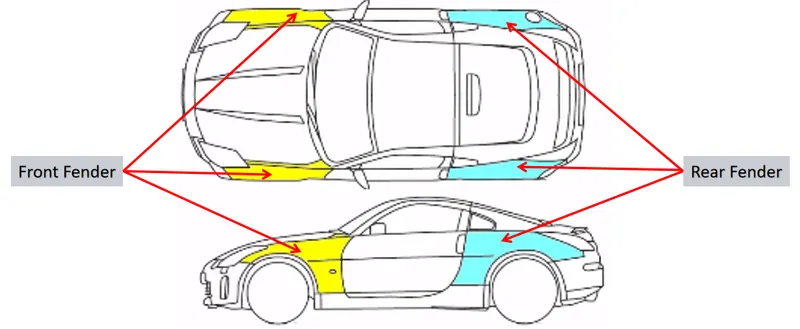
fig.1:front fender and rear fender
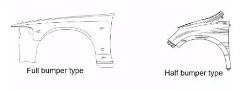
There are two types of fenders, full bumper type, and half bumper type.
In this report, we will study about:
1.Different standards of the front wheel arch area requirements.
a.Japanese Standards
b.European Standards
c.American Standards
2.Examining the given part considering the European Standards.
3.Checking whether the front fender wheel arch meets the standards.
1. Different standards of the wheel arch area requirements
Wheel Arch is the semi-circular part of the fender positioned above the wheel of the vehicle. The design of Wheel arch of a fender should be such that it must shield wheels and protect both passengers' compartment and pedestrians from projection of water, mud and stones.
The main purpose of the wheel arch area regulation is that seeing the front fender and tire from the top, the tire must be inside the fender by a certain distance.
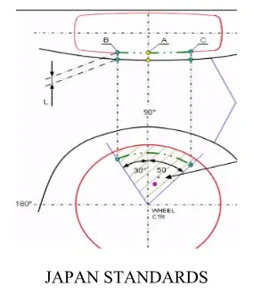
a.Japanese standards:According to the japan standards the distance between the wheel and the fender should be the minimum 5mm distance. all the three positions (i.e., at A, B, C from fender curvature)
b. European Standards
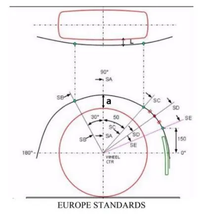
The value will be more than 10mm at 30 degree at forward and 50 degree at backward and line 150mm above x-axis and mid point between 50 degree and line above 150mm.
3.America standards:
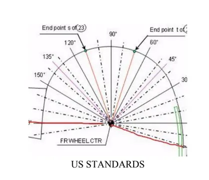
take a clearance check details on all positions from -100* to 100* and make the clearance check table.
All values should be greater than 5 mm to satisfy the regulations.
The value of 'a' shall be more than 5 mm at line 30* forward and 50* rearward from the central vertical axis of the wheel.
3. Examining the given part considering the European Standards
So lets consider European Standard
Procedure: Create a sketch is drawn on the wheel face and projected on the wheel arch at section SA, SB, SC, SD, and SE and then the clearance value at these section is measured.
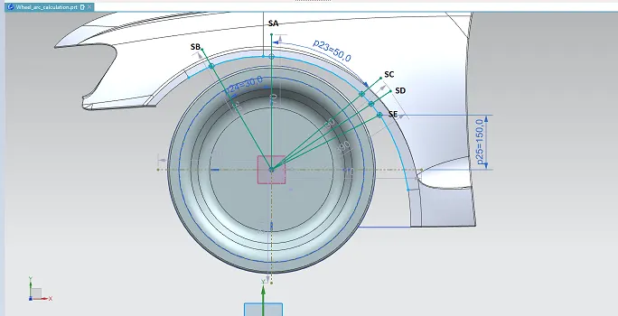
Obtaining the clearance value ‘L’ at section SA, SB, SC, SD and SE:
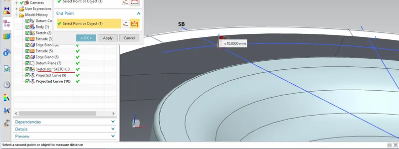
At Section SB:10.00mm
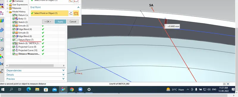
At Section SA: 9.9490mm
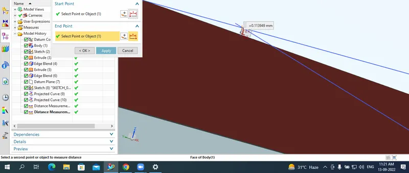
At Section SC: 0.113949mm
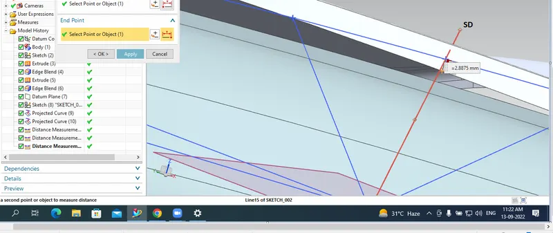
At Section SD: 2.8875mm
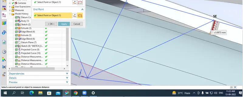
At Section SE: 5.9973mm
Observation Table:
|
Sections |
Clearance Measured (mm) |
Test Result |
|
SB |
10.000 |
Pass |
|
SA |
9.9490 |
Fail |
|
SC |
0.113949 |
Fail |
|
SD |
2.8875 |
Fail |
|
SE |
5.9973 |
Fail |