Fender Design - Wheel Arch Challenge
Car Fender Wheel Arch Challenge
Objective to Car Fender
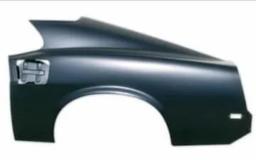
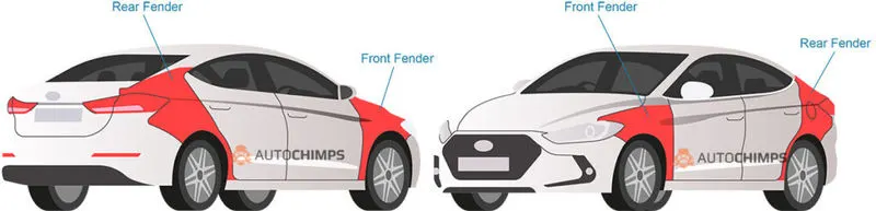
Fender is the term for the part of an automobile, motorcycle or other vehicle body that frames a wheel well (the fender underside). Its primary purpose is to prevent sand, mud, rocks, liquids, and other road spray from being thrown into the air by the rotating tire. Fenders are typically rigid and can be damaged by contact with the road surface.
Introduction to Wheel Arc
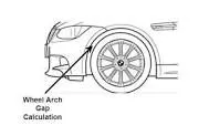
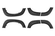
The shaped part of the bodywork of a car or other vehiclethat allows the wheel to be accessed, and in the case of front wheels, enable them to be steered.
Crash Analysis
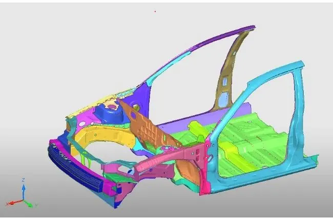
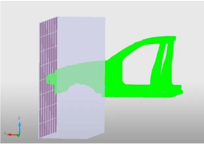
A crash simulation is a virtual recreation of a destructive crash test of a car or a highway guard rail system using a computer simulation in order to examine the level of safety of the car and its occupants. Crash simulations are used by automakers during computer-aided engineering (CAE) analysis for crashworthiness in the computer-aided design (CAD) process of modeling new cars. During a crash simulation, the kinetic energy, or energy of motion, that a vehicle has before the impact is transformed into deformation energy, mostly by plastic deformation (plasticity) of the car body material (Body in White), at the end of the impact.
Regulations for Fender Design
Based on crash analysis report some regulations are formulated for Fender Design by different standard organisations keeping in view pedestrain and passenger safety.
Japan Requirements for Fender Wheel Arch
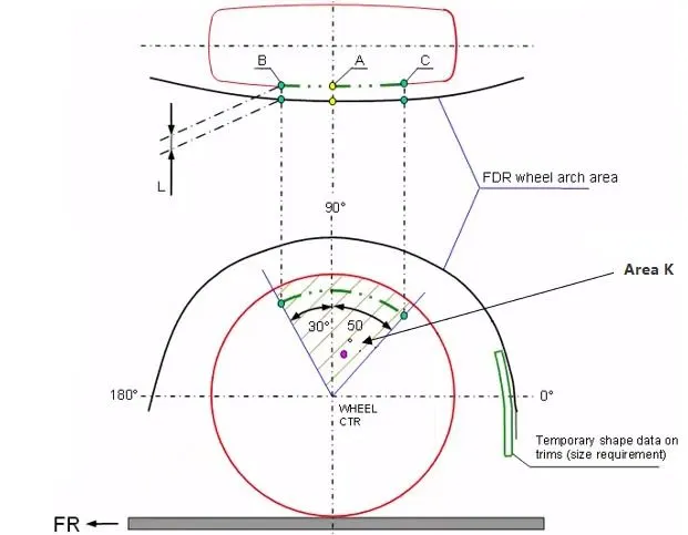
- Measure clearance L of tire, hub, cap, and fender in three different positions within area K and produce clearance check chart to validate.
- Clearance must be greater than 5mm in all the three positions.
- Wheel guard requirement: the value a shall be more than 5mm at a line 30° forward and 50° rearward from the central vertical axis of axis of wheel.
US STANDARDS REGULATION FOR FENDER WHEEL ARC
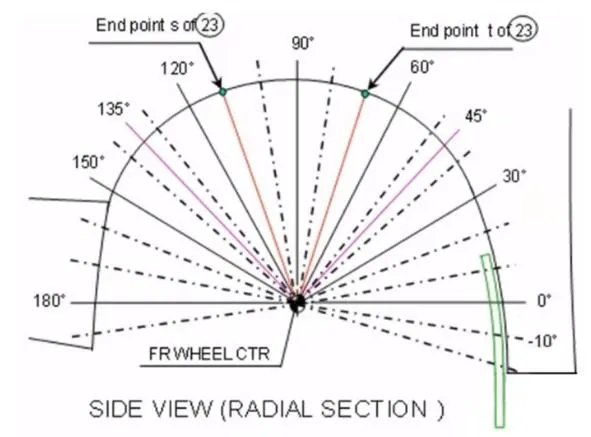
- Make clearance check details on all positions from -100° to 100° and make the clearance check table.
- All values should be greater than 5mm to satisfy the regulation.
- The value of ‘a’ shall be more than 5mm at a line 30° forward and 50° rearward from the central vertical axis of axis of wheel.
EUROPEAN REGULATION
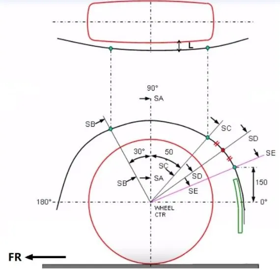
Measure CL L at section SA-SA-SB-SB-SC-SC-SD-SD-SE-SE and produce CL check chart to validate.
- At all five sections the CL L value should be greater than 10mm to satisfy the European regulations.
- Wheel guard requirement: the value of ‘a’ shall be more than 5mm at a line 30° forward and 50° rearward from the central vertical axis of axis of wheel.
Steps For Checking given Wheel Arch as per European Standards
According to the European standards, the design fender and wheel arc should pass the wheel guard requirement procedures.
- To start the test, first create a plane with origin as center of the wheel plane and draw two perpendicular axis.
- Then sketch using lines along with given dimensions as SA, SB, SC, SD and SE. SB is 30 degrees from SA on left side while SC is 50 degrees from SA on right side. Point E is at distance of 150 mm from horizontal axis. Point D is midpoint of arc CE.
- After sketching SA, SB, SC, SD and SE plot intersection points on the Fender face.
- Then use measure distance tool and calculate the clearance between sketch lines and wheel arc.
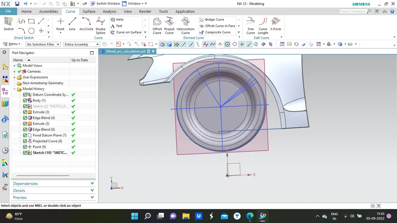
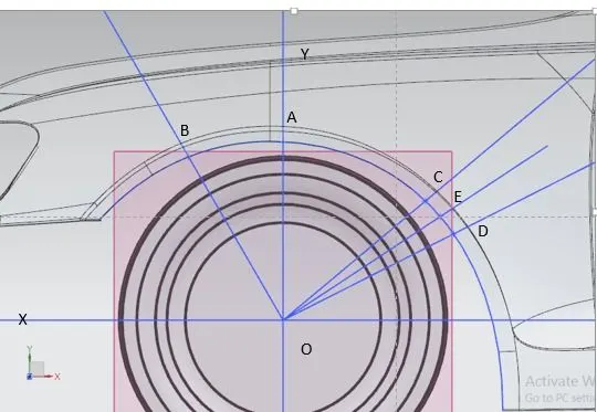
Measuring the distance from the wheel arch to the wheel tyre
1.The clearance between SA line and wheel arc is 9.9490mm.
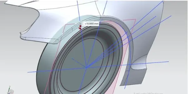
2.The clearance between SB line and wheel arc is 10mm.
3.The clearance between SC line and wheel arc is 0.113949mm.
4.The clearance between SD line and wheel arc is 2.8875mm.
5.The clearance between SE line and wheel arc is 5.9973mm.
Conclusion
From the above results we can conclude that the fender does not pass the European regulations, as the minimum clearance L between the fender wheel arch and wheel for vehicle and pedestrian safety is 10mm and this design does not meet the requirement.