Fender Design - Wheel Arch Challenge
Aim:
To calculate the Fender Wheel Arch area , to pass the European standards.
Objective:
Create the intersection point according to given degree angle.Follow the European standards to prove the design is valid. Tabulate the result to conculde the final result.For conclude weather pass or fails standard
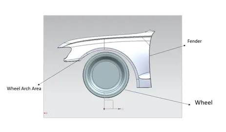
What is fender
Fender is the American English term for the part of an automobile, motorcycle or other vehicle body that frames a wheel well (the fender underside). Its primary purpose is to prevent sand, mud, rocks, liquids, and other road spray from being thrown into the air by the rotating tire. Fenders are typically rigid and can be damaged by contact with the road surface.
Sticky materials, such as mud, may adhere to the smooth outer tire surface, while smooth loose objects, such as stones, can become temporarily embedded in the tread grooves as the tire rolls over the ground. These materials can be ejected from the surface of the tire at high velocity as the tire imparts kinetic energy to the attached objects. For a vehicle moving forward, the top of the tire is rotating upward and forward, and can throw objects into the air at other vehicles or pedestrians in front of the vehicle.
Fender Wheel Arch Area:
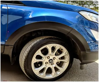
The wheel arch is the semicircular part positioned above the wheel of a vehicle. It is an integrated part of a fender assembly. The wheel arch area have some standard specification to measure the clearance between the tire and fender. If the tire lies outside the fender, it does more chipping cause a damage to pedestrian and also to car. To have a pedestrian safety in mind, we need to position the tire inside the fender. For that we have certain standard regulations.of it
- Japan Regulation
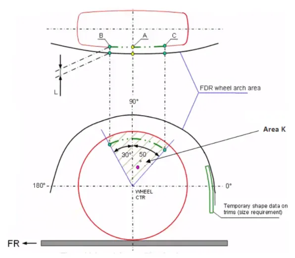
- The clearance ‘L’ for tire, hub, cap and fender is to be measured within area K and create clearance check chart to validate
- The value of L should be greater than 5mm at all positions
- Wheel guard requirement: The value of ‘a’ should be more than 5mm at line 30° forward and 50° rearwards from the central vertical axis of the wheel
The value will be more than 5mm at 30 degree at forward and 50 degree at the central vertical line.
- US Regulation
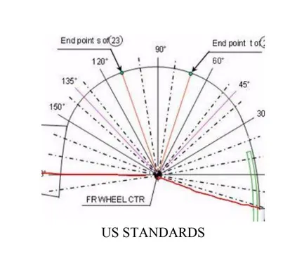
- Clearance ‘L’ is to be checked at all positions from -100° to 100° and create clearance check chart to validate
- The value of L should be greater than 5mm to satisfy the regulations
- Wheel guard requirement: The value of ‘a’ should be more than 5mm at line 30° forward and 50° rearwards from the central vertical axis of the wheel
The value will be more than 5mm at line 30 degree forward and 50 degree central vertical axis.
- European regulation
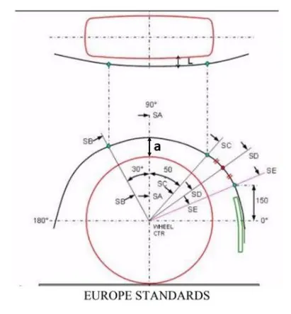
- The Clearance ‘L’ should be measured at sections SA-SA, SB-SB, SC-SC, SD-SD and SE-SE and create clearance check chart to validate
- At all the five sections the value of L should be greater than 10mm to satisfy the European Regulations
- Wheel guard requirement: The value of ‘a’ should be more than 5mm at line 30° forward and 50° rearwards from the central vertical axis of the wheel
The value will be more than 10mm at 30 degree at forward and 50 degree at line above150 mm.
- Design Criteria has been followed as follows
For calculation of clearance between Wheel Arch and Wheel we have to create a sketch on the outer most face of the wheel. The procedure of which is given below.
- A Datum Plane is created at the outermost face of the wheel
- The sketch is created on the new Datum Plane
- A Horizontal line is drawn across the centre of the wheel
- A perpendicular line SA is dropped at the centre of the wheel
- Two lines SB and SC are created at 30° forward of SA and 50° rearward of SA respectively
- A point is created 150mm vertically above the centre line
- A line SE is drawn from the wheel centre and passes from the point created
- Another line SD is drawn from the centre of the wheel and in the middle of lines SC and SE
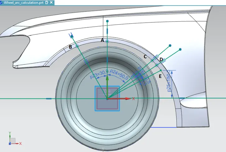
- Obtaining the clearance L at the designated 5 points of wheel arch
- SA
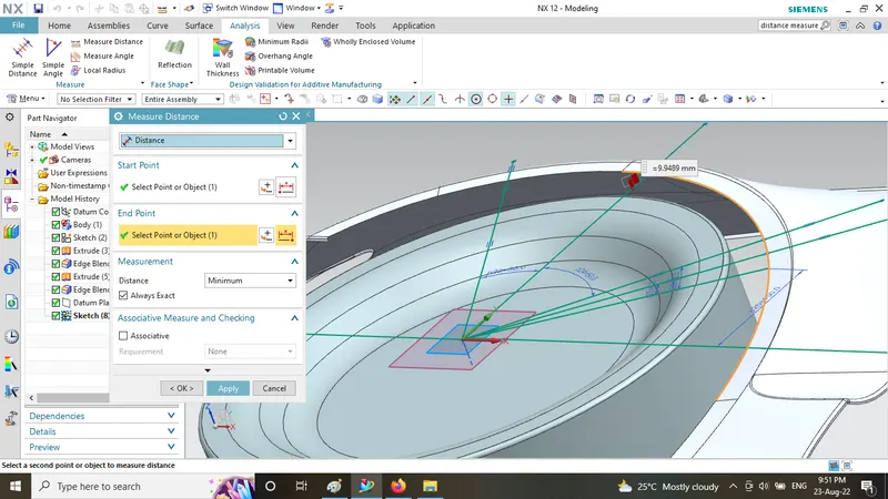
- ) Clearance 'L' at SA
L = 9.94
- SB
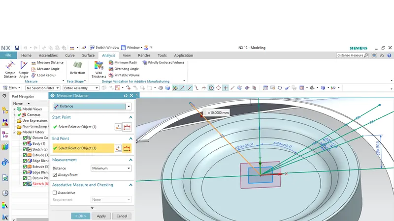
- ) Clearance 'L' at SB
- L = 10mm
- SC
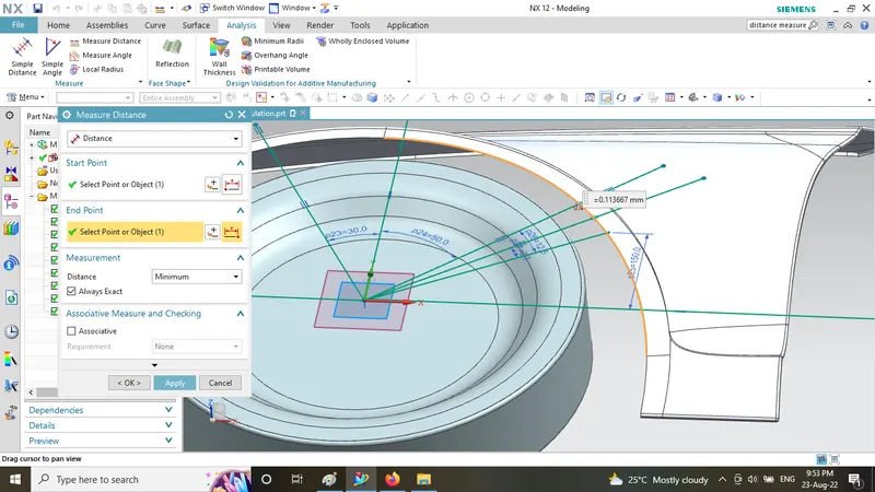
iii.) Clearance 'L' at SC
L = 0.11367mm
- SD
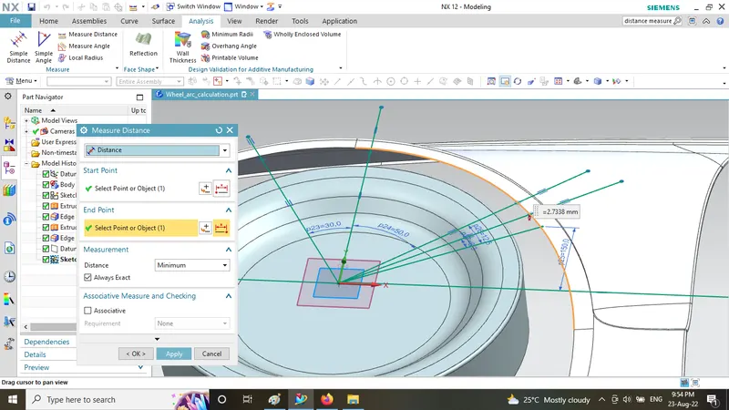
iv.) Clearance 'L' at SD
L = -2.736mm
- SE
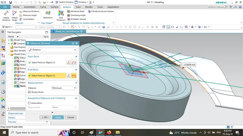
v.) Clearance 'L' at SE
L = -5.6629mm
Measuring the clearance value'a' for Wheel Guard Requirement
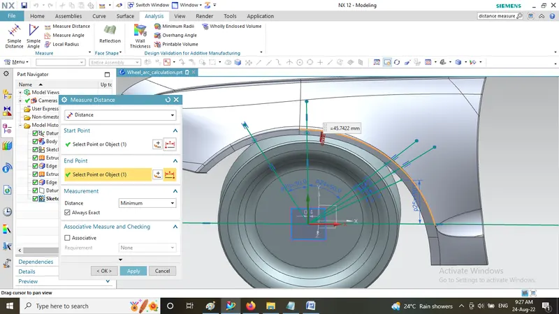
i.) Clearance 'a' at line SA
45.74mm
Observation in tabular form table for measurement over each area
|
Section |
Clearance required(mm) |
Observed Clearance(mm) |
Result |
|
SA |
10 |
9.94 |
Fail |
|
SB |
10 |
10 |
Pass |
|
SC |
10 |
0.1136 |
Fail |
|
SD |
10 |
-2.736 |
Fail |
|
SE |
10 |
-5.6629 |
Fail |
Conclusion =
Observed above calculation of the given fender wheel arch design will not pass the European standard in the position SA, SC, SD and SE has a clearance less than 10mm which is the minimum requirement for European standards.
The values at A,C,D and E sections are not as per standard
The car fails as of the european standard