Fender Design - Wheel Arch Challenge
OBJECTIVE:
To study the standard and regulations for fender design of wheel arch and analyse the data which is given in the question whether the wheel arc area will pass the standards or not.
There are various standard which normally varies by region and their road structure like japanese,U.S AND europe,here we take european standard.
INTRODUCTION TO FENDER:
A fender is the part of a car, truck, motorcycle, or other vehicles that frames or covers a wheel well. Its main purpose is to prevent debris, rocks, mud, liquids, sand, and other road debris from getting thrown in the air while the tires roated
The “fender” typically refers to the front panel that covers the front wheels, and the “quarter panel” typically refers to the rear panel that covers the wheel that also includes the roof pillar.
- The fender also reduces the pedestrian injury when there is a pedestrian vehicle collision and prevent throwing up of debris to nearby vehicles.
- Usually the front fender is designed seperately,the rear fender come along with the body structure.
- Pedestrian safety is also considered while designing wheel arch in fender since the debris in wheel should'nt hit them in the motion of the car.
-
The fender car part is the body kit or body part installed on the left and right sides of the vehicle. Manufacturers usually attach fenders to the wheel arches. There are different reasons why they are a requirement in vehicles. One obvious reason is to improve the aesthetics of the vehicle.
-
Fenders also enhance the car’s aerodynamics.
- Full-bumper type-
Full fender type is traditional type of fender where more material consumption is observed. This type is used in old design of automobiles where it increases the overall weight and thus reduces performance. The maintenance also relatively more due to more surface.
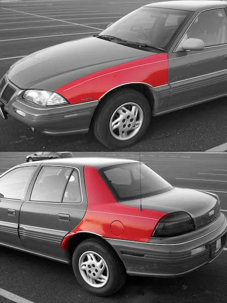
Front fender and Rear fender (quarter panel)
Half-bumper type-Half fender type is modern design where less material consumption is observed, so productivity increases by reducing size of blank and thus providing more performance. The maintenance also relatively low compared to full bumper type.
FENDER DESIGN CONSIDERATIONS:
- Drip Area
- Wheel arch
- Baffle and ORVM mount area
- frontal crash regulation and requirements.
STANDARDS FOR DESIGNING FRONT FENDER:
European standard for wheel arch-
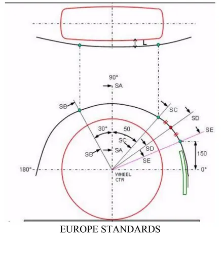
According to european standard clearance length for the wheel arch will be 10mm.
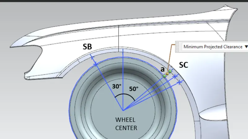
wheel CTR is wheel center.SA,SB,SC,SD,SE are the points on the wheel from where it is projected to the wheel arch to measure the distance.
wheel guard requirement: the value a shall be more than 5 mm at a line 30* forward and 50* rearward from the central vertical axis of axis of wheel.
Japan Requirements for fender wheel arch:
- measure clearence L of tire , hub, cap & fender in three different positions within area K and produce clearance check chart to validate.
- clearance must be greater than 5mm in all the three positions.
- wheel guard requirement: the value a shall be more than 5 mm at a line 30* forward and 50* rearward from the central vertical axis of axis of wheel.
- US Standards regulation for fender wheel arch:
- Make clearance check details on all positions from -100* to 100* & make the clearance check table.
- all values should be greater than 5mm to satisfy the regulation.
- the value of 'a' shall be more than 5mm at a line 30* forward and 50* rearward from the central vertical axis of axis of wheel.
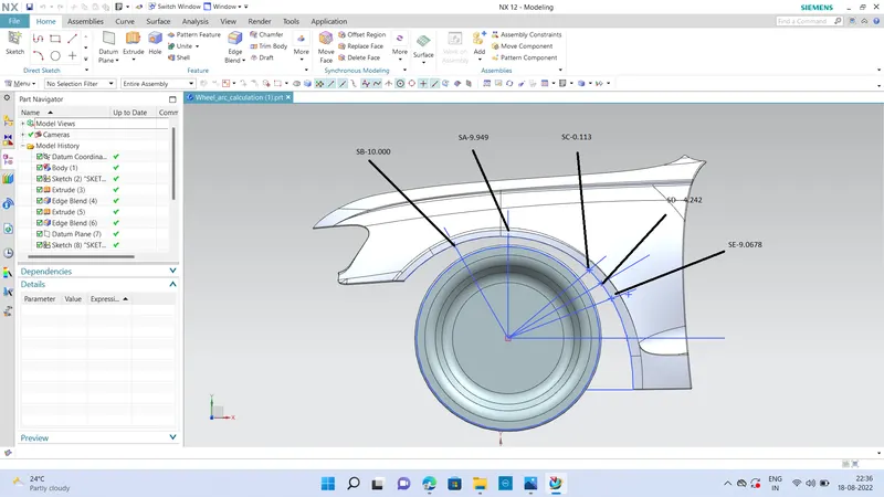
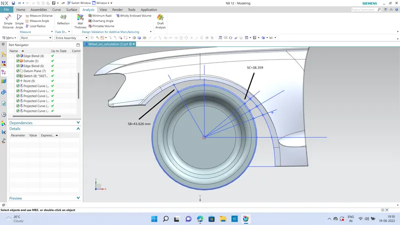
- According to european std calculate fende distance (L)
- L-The distance measured from most outside point of tire to the lower point of fender According to europian std value L=10 mm maintain .if this value is not same then provide feedback to fender designer
- All Values in mm SB=30 degree SA= Neutral Axis SC=50 degree
-
Sr Points Measured value compare with std value Result 1 SB 10.000=10.000 PASS 2 SA 9.9490<10.000 FAIL 3 SC 0.113 < 10.000 FAIL 4 SD -4.2426<10.000 FAIL - Result-need to be change the fender design cause 'L' value is not perfect for at point SA,SC,SD
- A-The distance measured from most outside diameter of tire to the near fender point at perticular point. when seeing left side or right side view
- the value 'A' shall be more than 5 mm at a line 30* forward and 50* rearward from the central vertical axis of axis of wheel.
-
Sr Points Measured value compare with std value Result 1 SB 43.626 >5 mm PASS 2 SC 38.359> 5 mm PASS - Result-no need to change the value