Fender Design - Wheel Arch Challenge
WHEEL ARCH-CALCULATION
OBJECTIVE:
To calculate the wheel arch gap at required points as per the European standard.
SOFTWARE USED:
Siemens NX12.0
WHAT IS WHEEL ARCH?
Wheel Arch is the semi-circular part of the fender positioned above the wheel of the vehicle. The design of the wheel arch should be in such a way that it shields wheels and protect both passenger’s compartment, BIW and pedestrian’s from the chipping of water, mud and stones. The wheel arch has some standard clearance values. These values varies from region to region based upon the road and weather conditions. Followings are the regulations followed by the automobile industries.
WHEEL ARCH REGULATIONS:
Japan
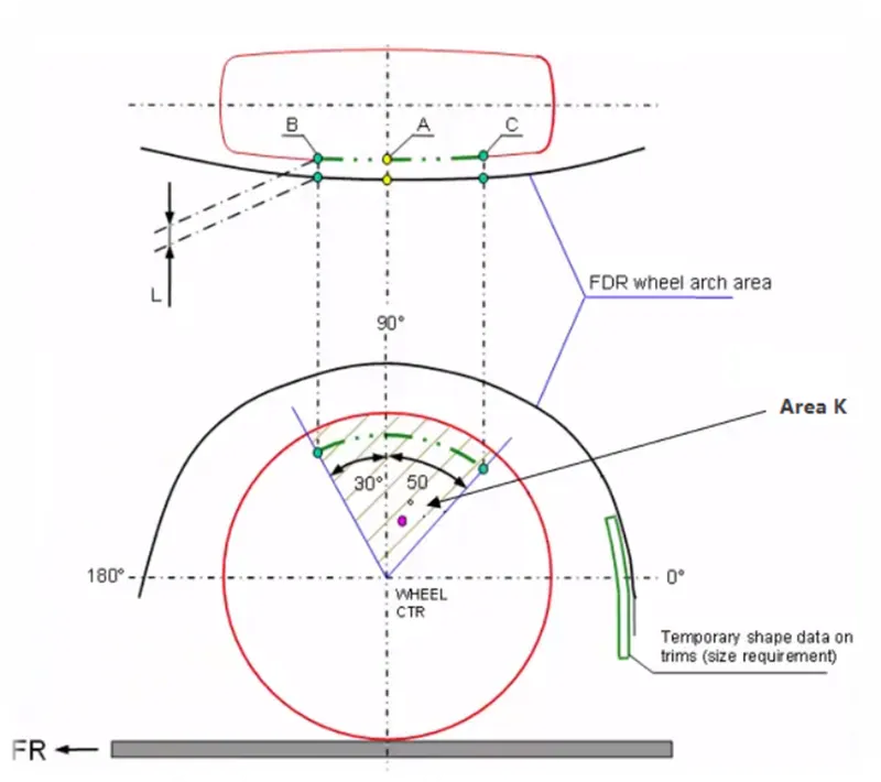
- The clearance gap ‘L’ is to be measured within the “area K” at 30° forward and 50° backward from the central vertical axis of the wheel.
- The value ‘L’ should be greater than 5mm within the area.
United States
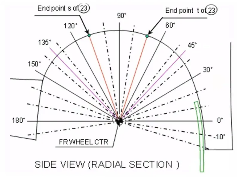
- The clearance gap ‘L’ should be measured at positions from -20° to 190°.
- The value of ‘L’ should be greater than 5mm at every 10° within the checked positions.
Europe
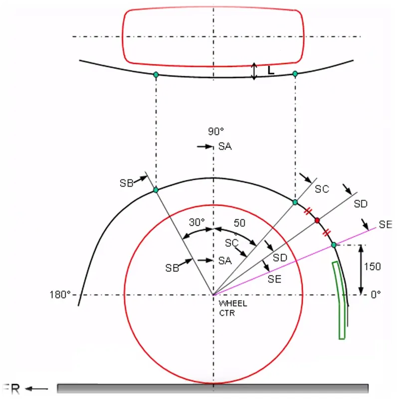
- The clearance gap ‘L’ should be measured at positions SA, SB, SC, SD and SE
- The value of ‘L’ should be greater than 10mm to satisfy European regulation.
WHEEL ARCH CALCULATION PROCEDURE-EUROPEAN REGULATION:
- A datum plane is created at the outermost face of the wheel.
- A sketch is created in new datum plane and horizontal, vertical axis are plotted.
- Curves are offset at distance 0mm from the edges of the given fender.
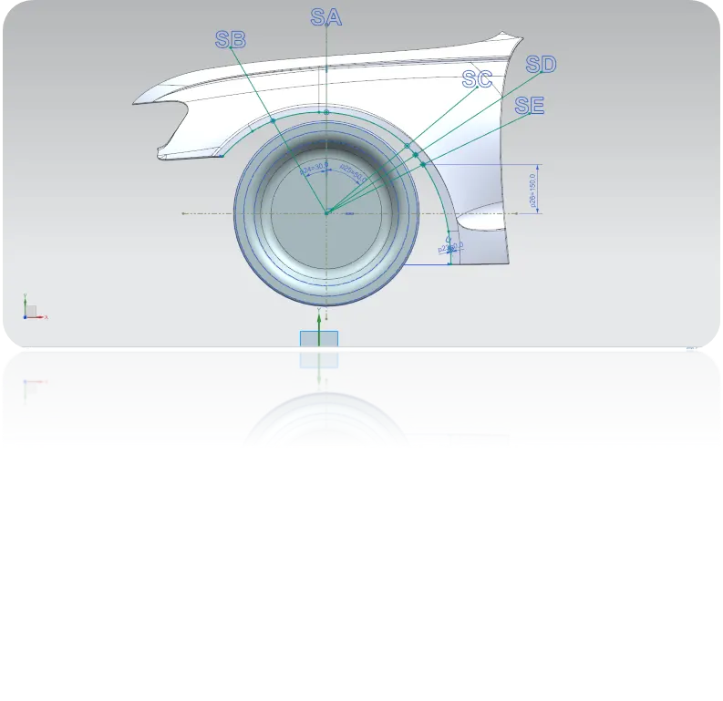
- Lines are created at 30° forward(SB) and 50° backward(SC) from the central vertical axis to the offset curves.
- A point(SE) is placed on the offset curve at a distance 150mm from the horizontal axis. Another point SD is created on the offset curve in between the points SC and SE.
- Lines are created from the points SD and SE to the central axis.
SKETCH:
CLEARANCE GAP ‘L’ AT DESIGNATED POINTS:
The clearance gap L is measured at points SA, SB, SC, SD and SE.
At point SA
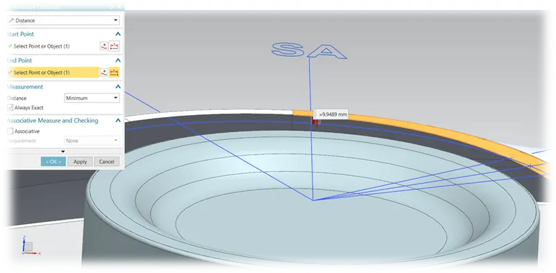
L=9.9489mm
At point SB
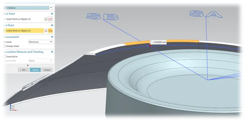
L=10.0mm
At point SC
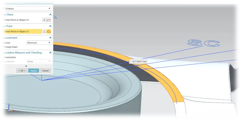
L=-0.112637mm
At point SD
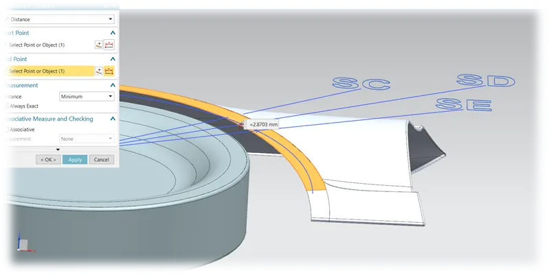
L=-2.8703mm
At point SE
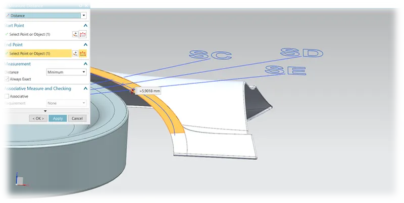
L=-5.9018mm
OBSERCATION TABLE:
|
Sections |
Clearance measured(mm) |
Results |
|
SA |
9.9mm |
FAIL |
|
SB |
10.0mm |
PASS |
|
SC |
-0.11mm |
FAIL |
|
SD |
-2.87mm |
FAIL |
|
SE |
-5.90mm |
FAIL |
Note: Negative sign indicates the fender curvature lies below the wheel surface.
CONCLUSION:
The wheel arc calculations are tabulated, most of the points fails to meet the European regulations. The curvature of the fender should be modified to meets the standards as much as possible.