Fender Design Challenge
DESIGN OF FENDER
OBJECTIVE:
To design the car’s front fender from the given skin data and design the drip mounting area according to the given master sketch.
SOFTWARE USED:
Siemens NX 12.0
WHAT IS FENDER?
Fender is the American English term for the part of an automobile, motorcycle, or other vehicle body that frames a wheel well. Actually, it is a part that is in contact with the different parts of the vehicle like the A-pillar, sill, etc. Typically fenders are rigid and house the wheels, inner body parts both at the front and back sides of the vehicle.
This fender plays a major role in pedestrian safety while a car is in motion. When it is in motion the wheel carryover the small stones, mud particle and throw away which may harm the pedestrians and also the components of engine compartment. So while designing these considerations are to be taken into account. A pair of front and rear fenders can be found on each side of a vehicle.
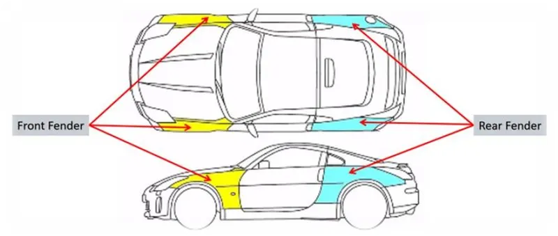
TYPES OF FENDER:
Fenders are of two types, full bumper and half bumper types.
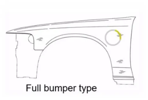
- Full bumper type
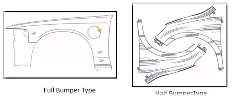
Full bumper type covers the entire wheel of the vehicle thus reduces the space for the plastic bumper mounts. The manufacturing cost are also high in this types, from a full blank one fender can be produced. The wastage of materials are also quit high.
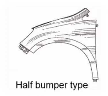
- Half bumper type
The half bumper type are reduced in weight thus increases the area for the plastic bumper mounting and also reduces the vehicle weight. From a single blank two half bumper fenders can be produced. The cost reduction and scrap management can be improved by producing this kind of fenders.
Blanks for full and half fenders
DESIGN PARAMETERS:
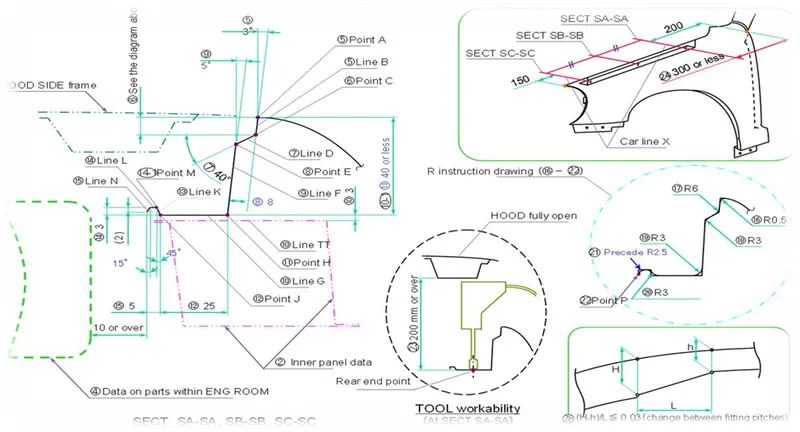
- From the master sketch the drip area is designed according to the given parameters.
- The drip area is located 150mm from the bumper side and 160mm from the A-pillar region.
- The total height of the drip area is maintained within 40mm.
- The tool workability is maintained above 200mm when the hood is in open condition.
- Above 10mm clearance is maintained from the edge of the drip area to the engine room.
- All the emboss drafting angle is maintained at 8degree.
Given data
Class A-surface
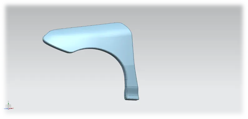
From the given surface fender is designed with respecct to the design parameters.
FENDER MOUNTS:
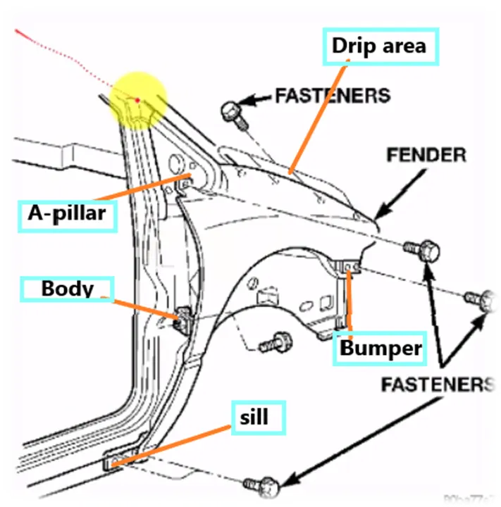
- Bumper mounting area
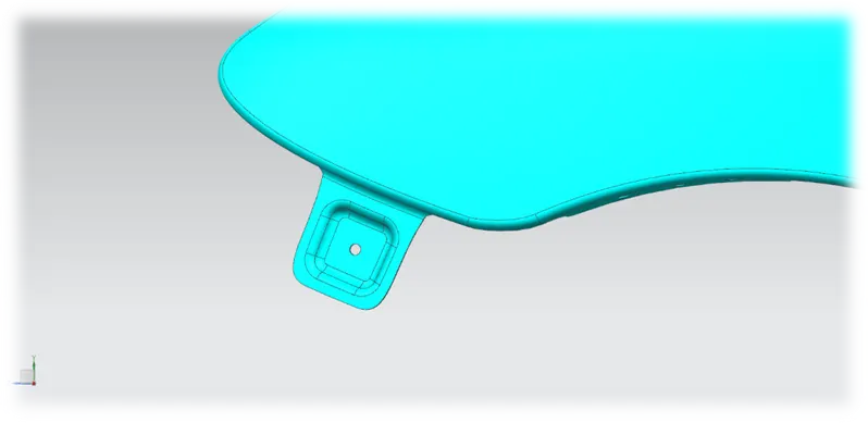
- A-pillar mounting area
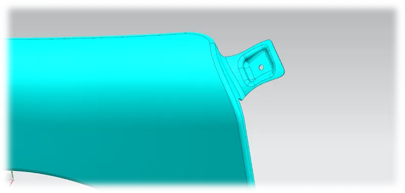
- Sill mounting area
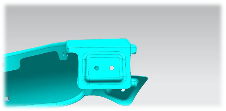
- Drip mounting area
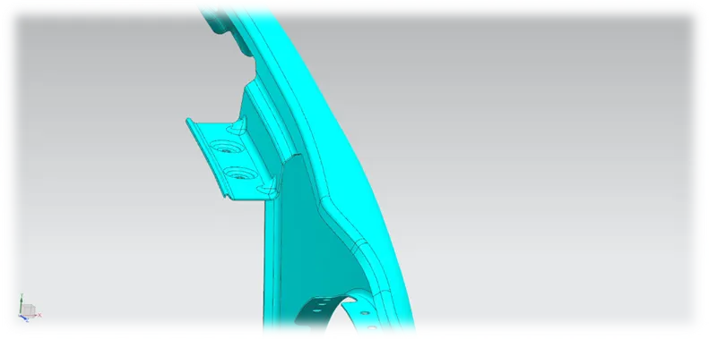
- Baffle mounting area
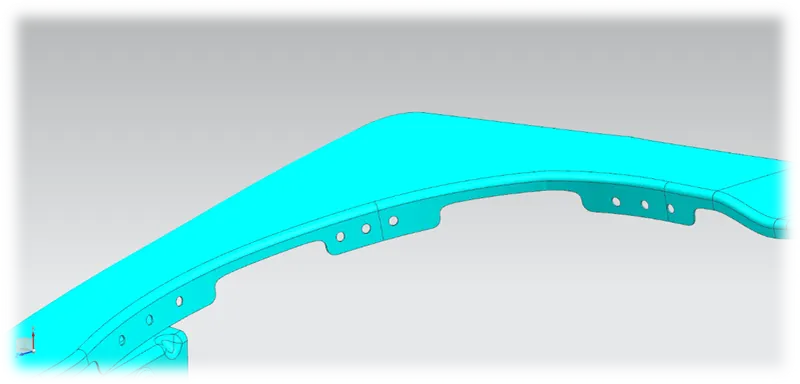
MANUFACTURINF PROCESS:
- Snipping or blanking operation should be done for taking the piece of a sheet from the long rolled one.
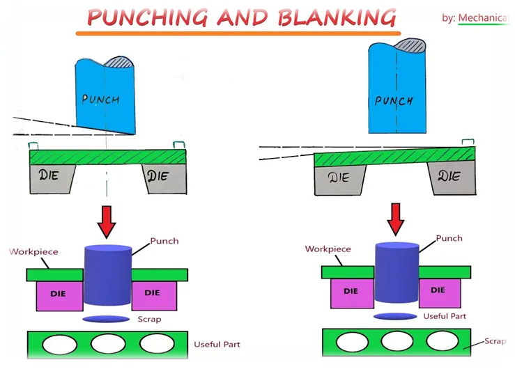
- Bending and re-striking are performed to get the desired shape.
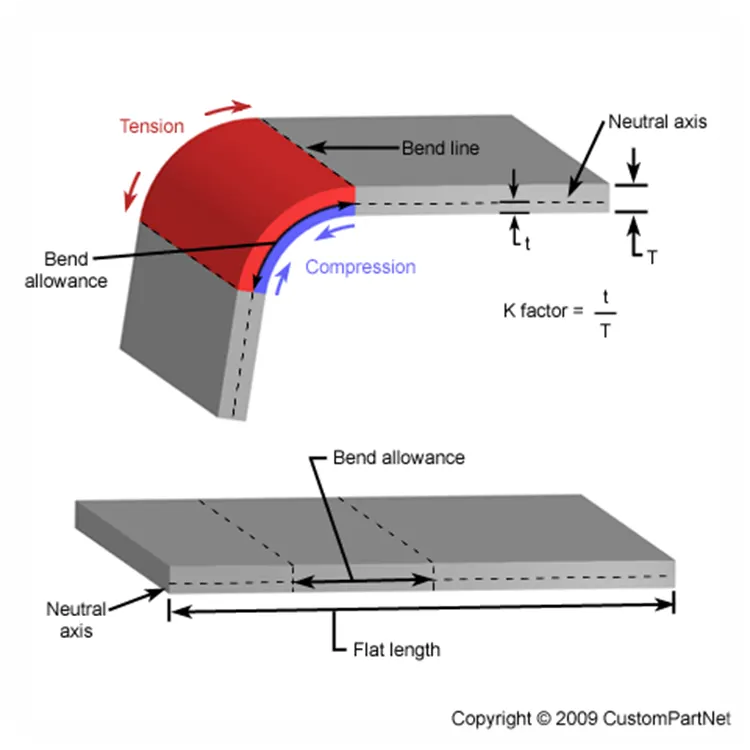
- Trimming is performed to trim the unwanted sections from the working sheet.
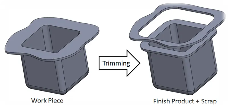
- Piercing should be performed to make the required holes on the sheet.
- Embosses are created by doing the deep drawing by considering the draft angle.
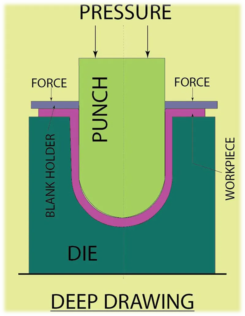
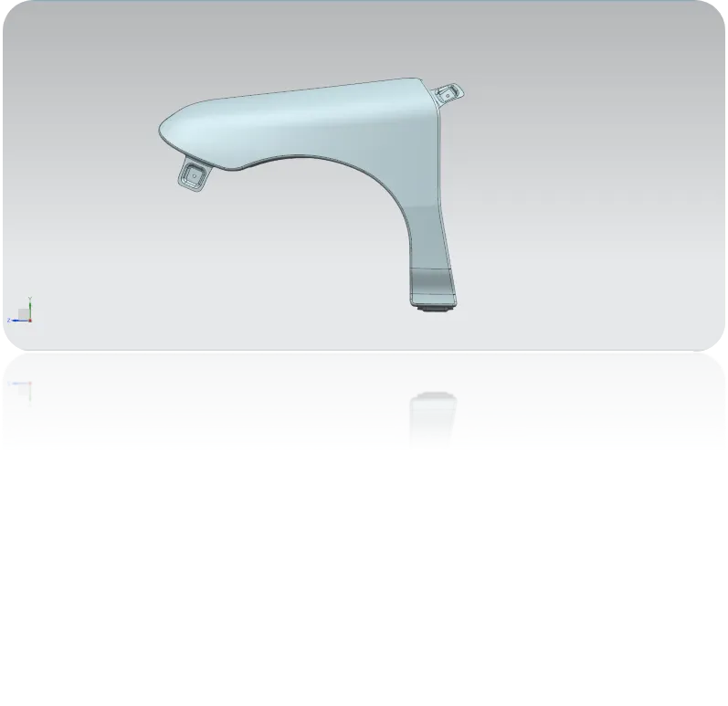
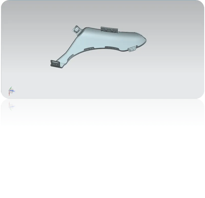
FINAL DESIGN:
CONCLUSION:
Thus the front fender is designed with respect to the parameters and the design, manufacturing consideration.