Fender Design - Wheel Arch Challenge
FENDER WHEEL ARCH
Aim:
To give the details measure of clearance to give part .and also give detail report of other countries fender wheel arch clearance. Finally, analysis the dimensions for the give diagram for other fender regulations
Master section:
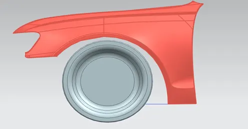
What is fender:
Fender is the American English term for the part of an automobile, motorcycle or other vehicle body that frames a wheel well (the fender underside). In British English, the fender is called the wing. (This may refer to either the front or rear fenders). the primary purpose of the fender is to prevent sand, mud, rocks, liquids, and other road spray from being thrown into the air by the rotating tire. Fenders are typically rigid and can be damaged by contact with the road surface. And it located over the wheels of the vehicle – two in the front right and left, and two in the rear right and left of your vehicle.
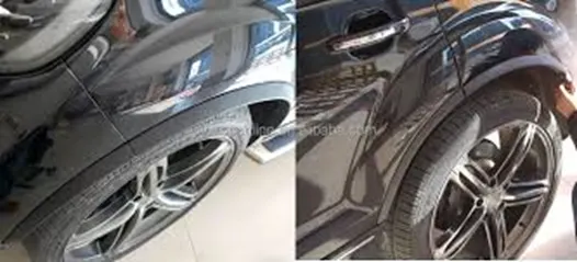
Many people think that bumpers and fenders are the same part of the car. In actuality, the bumper is a plastic component that covers the front and back of your vehicle, while the fender is a metal structure that frames the wheel well
Type:
- Full bumper type fender
- Half bumper type fender
Full bumper type fender:
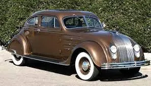
In early stage of automobile, the full bumper type fender is used the main purpose is to prevent mud, sand, rock, liquid and other road spray to hit the car component. In this type there were full metal frame cover the car type and is the one of the drawbacks of the type
Half bumper type fender:
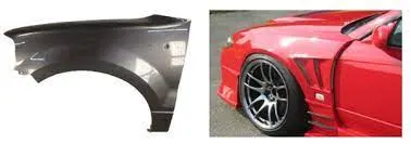
This half bumper type fender is considered as the evaluation of full bumper type fender. In this bumper there were only one half of the bumper were used for vehicles.
Why we go for this type is mainly for reduce the use of material. When we reduce the weight of the vehicle it automatically increases the speed of car
Regulations
As a general rule, when your trailer is loaded to its full capacity, there should be a minimum clearance of 3 inches between the top of your tire and the underside of your fender. This should give you adequate clearance for potholes and bumps. If you want to get precise, on an underslung trailer (the springs are mounted under the axle), you should measure the distance between the bottom of your frame and the top of your axle. Add two inches to that measurement and you should have adequate clearance when your trailer is fully loaded.
Tyre Clarence
We can define tire clearance as the minimum of the distance(s) from the tire to the object(s) its being measured with respect to. That is, for each item in the set of objects, measure the distance between the closest point on the tire and the object
US regulation:
As per NHTSA issue federal motor vehicle safety standards (FMVSS), the clearance between tyre and fender must greater then 5mm. the projected points to be measured are at the angles -30 degree forward to 180 degrees respectively. Thus, each position is divided into 10 degrees. There were 21 points must measure for us regulation
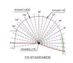
Japanese regulation:
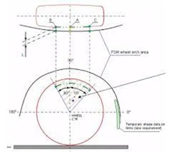
As per the Japanese regulation the clearance between tyre and fender must be greater than 5mm the projected points to be measures are at the angle of 300 forward and 500 backwards respectively. In these wheels arch standard, there is 3 points we must measure that is A, B, C.
Wheel arch calculation:
In the give diagram we going to measure the clarence of the wheel and give detail report. In the diagram we measure 3-point name are A, B, C.
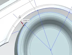
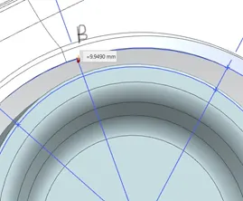
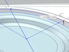
Table:
|
Measured points |
A |
B |
C |
|
Required length |
5 |
5 |
5 |
|
Actual length |
10 |
9.9490 |
2.5563 |
|
remarks |
Pass |
Pass |
Fail |
Conclusion:
In the given diagram there is two points of A, B was satisfying the requirement and other will not. Hence Japanese standard the given diagram we change fender dimension otherwise this model will fail
European regulation
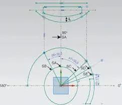
As per the European regulation, the clearance value between the fender and tyre surface must greater then 10mm. In that clearance we measure the 5 points at different angle. But there will be a 30 degree from 2 quarter and also 50 degrees from 1 quarter was important and other will measure from 1 quarter. And other will be 150 mm offset from the centre reference line and also the in between the 50 degrees.
Wheel calculation:
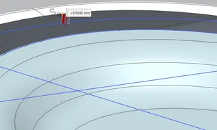
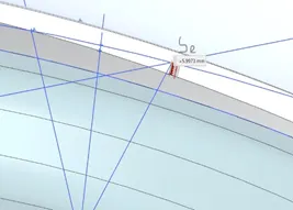
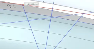
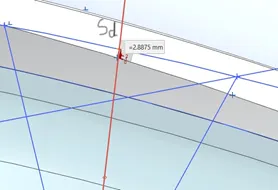
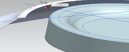
In the give diagram we going to measure the clarence of the wheel and give detail report. In the diagram we measure 5-point name are Sa, Sb Sc, Sd, Se
Table
|
Measured points |
Sa |
Sb |
Sc |
Sd |
Se |
|
Required length |
10 |
10 |
10 |
10 |
10 |
|
Actual length |
9.9490 |
10 |
2.5563 |
-2.8875 |
-5.9973 |
|
remarks |
Fail |
Pass |
Fail |
Fail |
Fail |
Measuring the value of ‘a’ at line 300 forward 2nd quarter from the central vertical axis of the wheel
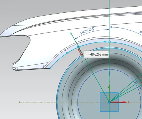
Measuring the value of ‘a’ at line 500 forward 1nd quarter from the central vertical axis of the wheel
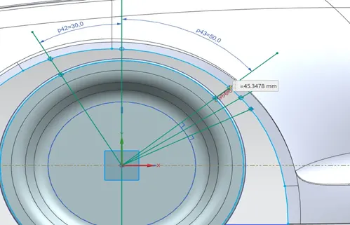
Table
|
Section |
Angle |
Clearance ‘a’ |
Remarks |
|
Sb |
300 |
48.6263 |
Pass |
|
Sc |
500 |
45.3478 |
Pass |
Conclusion:
In the above diagram there is only one point Sb was satisfying the requirement and other will not. Hence European standard the given diagram we change fender dimension otherwise this model will fail. But the clearance ‘a’ at the angle of 30 degree and 50 degree was more enough to pass the European standard.