Fender Design - Wheel Arch Challenge
Objective:
To measure the Wheel Arch gap at required points and check whether the car passes the European standard for the design provided.
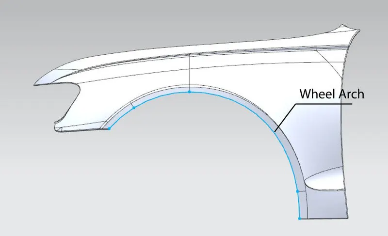
Fender - Wheel Arch:
The wheel arch is the arc-shaped cutout in the fender to house the wheels of the vehicle. Its basic functions are i) To protect pedestrians and other vehicles from getting injured by the debris thrown off at high speed by the tires, ii) To protect the engine compartment of the vehicle from the debris bombarded due to the high velocity of the tires. The blue line in the below-shown image is the wheel arch region.
Wheel Arch regulations:
There are a few sets of standards which if followed while designing the wheel arch region. It varies across the globe. The regulations are set based on road conditions and road safety factors.
1. Japan Regulations:
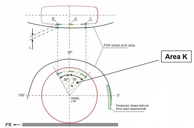
According to the japan regulations, from the vertical central axis through the wheel center,
- a 30-degree line is marked toward the front of the car.
- a 50-degree line is marked toward the rear of the car.
- The region between these two lines is called "Area K".
- These lines are projected and viewed from the top view and we get three regions, A, B, and C.
- At all three points, from the top view, the distance between the fender and the wheel should be a minimum of 5mm.
ii. European Regualtion:
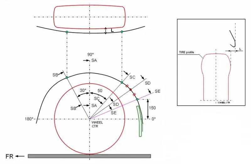
According to European regulation, from the vertical central axis through the wheel center,
- The vertical axis of the wheel is called "SA"
- a 30-degree line is marked toward the front of the car, this point is called "SB".
- a 50-degree line is marked toward the rear of the car, this point is called "SC".
- Another character line is drawn between the wheel center and the point in the wheel where the distance is 150mm from the horizontal axis of the wheel. This point is called "SE".
- A midpoint is marked between the points SC and SE, this point is called "SD".
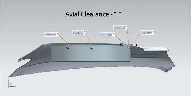
- These lines are projected and viewed from the top view (along the height of the car) and we get Five regions, SA, SB, SC, SD, and SE. The distance from those regions and the wheel arch line is measured to obtain Axial Clearance - L.
- These lines are projected and viewed from the front view (along the width of the car) and we get five regions, SA, SB, SC, SD, and SE. The distance from those regions and the wheel arch line is measured to obtain Radial Clearance - A.
- At all five points, both axial and radial clearance should be a minimum of 10mm.
iii. US Regulations:
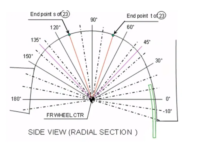
According to US regulations, from the vertical central axis through the wheel center,
- Two lines are drawn at -100 degrees and 100 degrees.
- In between those regions, at every 10-degree, a point is created.
- These points are projected and viewed from the top view
- At all those points, from the top view, the distance between the fender and the wheel should be a minimum of 5mm.
Analysis:
For this analysis, we are considering European Regulations.
- The wheel center is marked in the design file given.
- A vertical and horizontal axis is drawn with respect to the wheel center. The vertical Axis is called "SA"
- A 30-degree line is drawn towards the front from the vertical axis and it is called "SB"
- A 50-degree line is drawn towards the rear from the vertical axis and it is called "SC"
- On the rear side of the wheel, from the horizontal axis, a point is marked at 150mm and it is called "SD"
- A midpoint is marked in between the points SC and SD and it is called "SE"
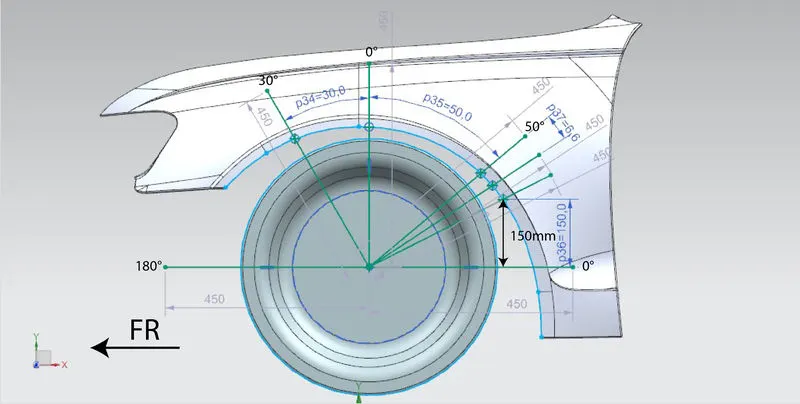
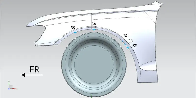
- All these points and the wheel arch area of the fender are projected into a plane that is normal to the Z-axis of the vehicle.
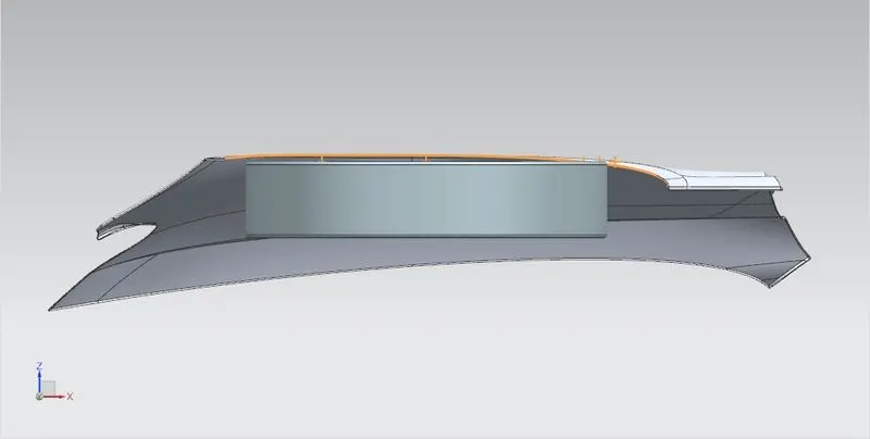
- The distance between those points and the wheel arch line is measured for clearance and the obtained value is known as "Axial Clearance - L".
- From the sketch created earlier, the distance between the wheel arch line and the wheel outline is measured along the points to find out the clearance, and the obtained value is known as "Radial Clearance - A".
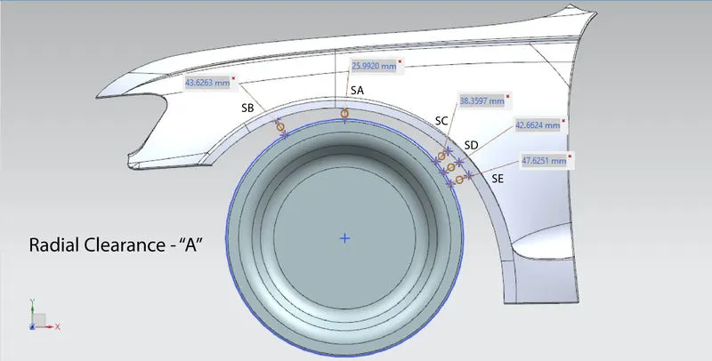
- Thus the Axial Clearance - L and radial Clearance - A is found.
Observation:
The measurements taken are tabulated and the following observations are made.
i. Axial Clearance - L:
The tabulation for axial clearance is given below.
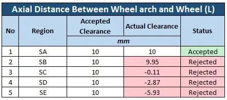
- In the axial clearance, only the region of SB satisfies the European Regulation standards.
- The points SA, SC, SD, and SE fall short of the minimum required clearance value and so it does not satisfy the European Regulation standards.
ii. Radial Clearance - A:
The tabulation for Radial Clearance is given below.
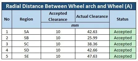
- In the radial clearance, the design provided is satisfying the minimum requirement of 10mm clearance in all the inspected regions.
Recommendation:
With the observation from our analysis, we will be recommending the following to the styling team.
- The axial clearance is very low when the wheel arch proceeds to the rear of the car, which should be increased in order to satisfy European regulatory standards.
- The curvature of the wheel arch along the width of the car should be altered by the styling team.
Attachments:
The design used for analysis along with the sketches has been attached for reference.