Fender Design
Prepare a report by explaining about Fender Design and its different mounts, manufacturing process and its design parameters
FENDER
A fender is a curved portion of car’s body that sits over and the house wheels
PURPOSE OF FENDER
The purpose of a fender is pretty simple. Its purpose is to keep mud, rocks, and other road debris from being thrown around by the tires. In other words, the fender is a housing for the wheels that keeps road debris contained. If there was nothing covering the wheels, all kinds of debris would be kicked up by the rotating tires.
There are two types of fenders:
- FULL BUMPER TYPE FENDER
- HALF BUMPER TYPE FENDER
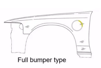
FULL BUMPER TYPE FENDER
In that full bumper type is the traditional type of fender where more material consumption is observed. This type is used in the old design of automobiles where it increases the overall weight and thus reduces performance. The maintenance also relatively more due to more surface
HALF BUMPER TYPE FENDER
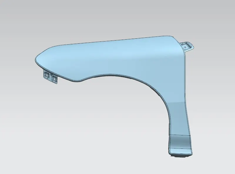
Half bumper type is the modern design where less material consumption is observed, so productivity increases by reducing the size of the blank and thus providing more performance. The maintenance also relatively low compared to the full bumper type. Mostly bumpers don’t give production to others suppliers ,for make it own
MOUNTING AREAS OF THE FENDER ARE
1.BODY
2.A PILLAR
3.SILL
4.COWL
5.DRIP AREA
BODY
It is an integral part of the fender and also has some mounting holes, the holes must be unique for manufacturing feasibility.
A PILLAR
The A -pillar is the structural pillar that combines the body to the roof. this makes the sides of the windshield rest. front fenders are fastened to the A -pillar to form a robust structure.
SILL
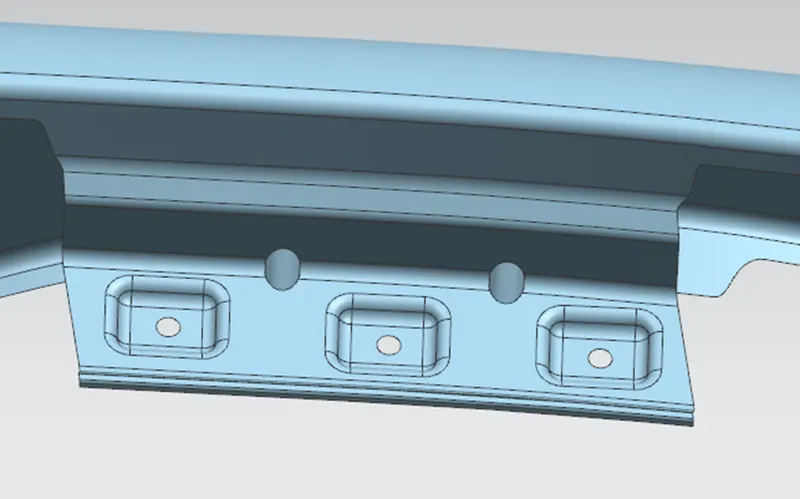
Sill is the panel located below the fender and also supporting the floor and may be used to combine the floor and the body. The bottom end of the fender is mounted on the sill body for reinforcement of the fender panel, thus the sill mounting position is designed with holes and emboss.
COWL
Cowl top part is the mounting part in fender. It carrying the viper motor and its instruments
DRIP AREA
Drip Area is the major part of the fender it has connected between the engine compartment and the fender. The rear end and the front end of the fender has some specified gap to be maintained. For the particular gap has been maintained for installing the cowl top part. When the drip surface is stamped 3 degrees must be secured for spring back. The fender drip area also mainly considers for the pedestrian safety.
THE STEPS FOLLOWED FOR MANUFACTURING THE FENDER
STEP 1: open straight snips plate: first select applicable cold coiling specification, cold coiling is opened flat; Then according to production material specification, will open cold coiling after flat and be cut into the iron plate of corresponding size; Finally, the iron plate after shear is cleaned to iron filings;
STEP 2: oil pressure, punch press: first iron plate is extended; Secondly to its trimming and punching; Then to its flanging and shaping; Finally, after shaping completes, then carry out one-off hole-piercing; Completed the making of lappet plate body
STEP3: The iron plate is stamped out to required outline blank (blanking); Then to completing the further moulding of iron plate of outline blank; Finally, it is carried out to punching;
STEP 4: Finally, the welding, trimming, and punching are to finalize the product
DESIGN PARAMETERS to be followed
- The drift area has maintained the gap of 150 mm front and 200 mm rear
- The extension of the sheet not above 40mm it makes Spring back effect
- All the corner of the sheet should be blend don’t leave sharp corner
- All edge should be blend
- The gap between the emboss and the end of sheet should have minimum 5mm gap
- Draft has maintained a minimum radius of 3 and above
- All holes should have minimum 5mm of flat surface
- Radius of blend should be 3mm or above
- A Hood and Fender should maintain the gap for open and closing
Designing steps for fender
- DRIP AREA
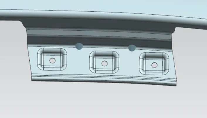
In the drip area has been created based on master data, and also it has ribs for strengthen the area
- A PILLAR
For particular designing of A Pillar have been noticed it is curvy part so the edges have to maintain the smoothness
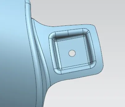
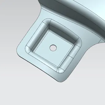
- BUMPER SIDE
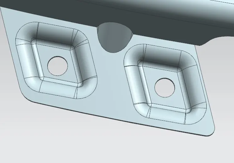
- SILL MOUNTING
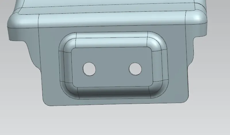
- BAFFLE MOUNTING
-
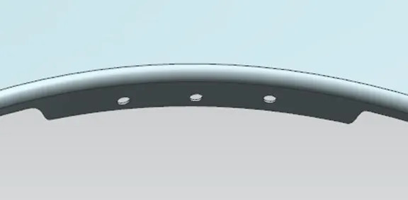
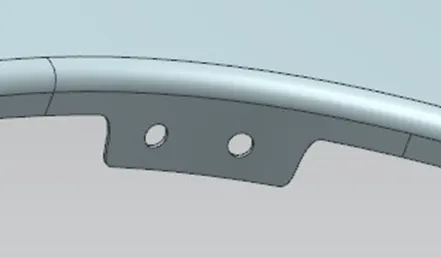
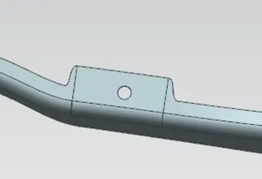
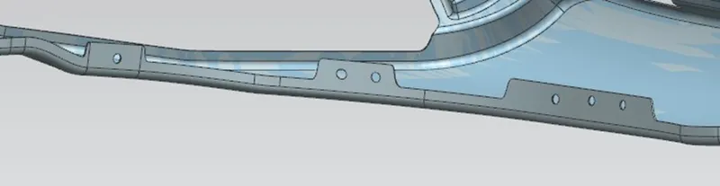
- OTHERS VIEW
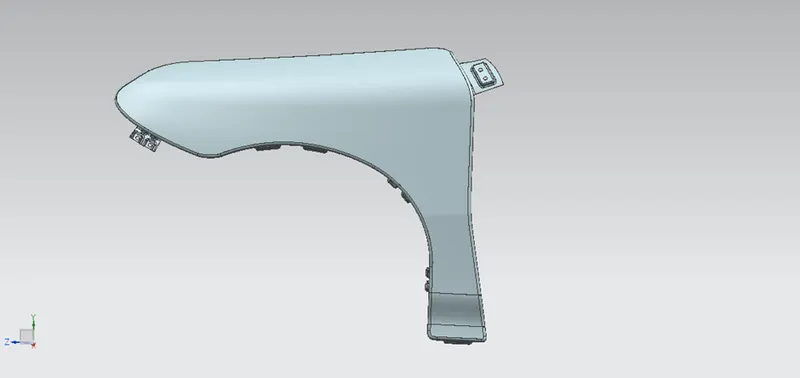
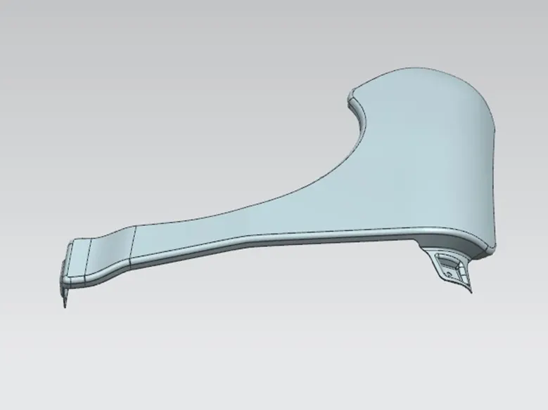
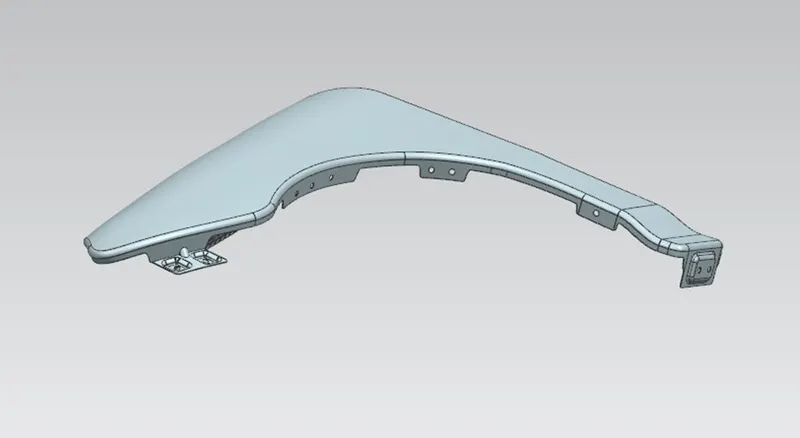
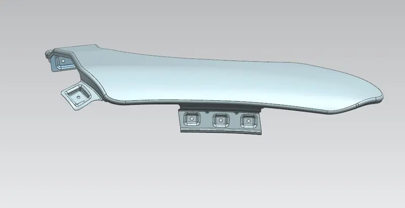
- CONCLUSION
- Finally the fender design and mounting points has been created with the help of parameters and master section by using the siemens NX CAD software