Fender Design - Wheel Arch Challenge
Objective:
To check the Wheel arc gap of the given front fender and conclude whether it satisfies European standards.
Fender:
A fender is a curved panel that sits above the wheels of a car, covers the engine component, and runs from the bumper to its doors. It protects the car by picking up all the dirt and other things on the road, which would otherwise damage the car.
Fenders are basically present to prevent any injuries to pedestrians.
Different fender wheel arch regulations:
1. Japanese Regulation
2. European regulation
3. US regulation
Japanese Regulation:
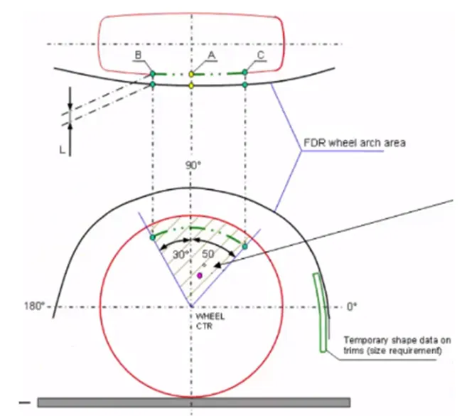
As per japanese standard the distance L need to be a miniumum of 5mm from the fender.
Steps:
1. From the wheel centerline lines are drawn to an angle of 50 and 30 degree.
2. The lines are projected to the top view.
3. The projected lines should be atleast 5mm inside the fender. (Wheel inside and fender outside).
European Regulation:
As per European standard the distance L need to be a miniumum of 10mm from the fender.
Steps:
1. From the wheel centerline, lines are drawn to an angle of 50 (SC) and 30 (SB) degree.
2. A line 150 mm from the horizontal wheel axis is intersected to the fender (SE).
3. A line is connected from the centerline to the above mentioned line (SE).
4. A symmetric line is drawn between SC and SE and connected to wheel centerline (SD)
5. The lines are projected to the top view.
6. The projected lines should be atleast 10mm inside the fender. (Wheel inside and fender outside).
US regulation:
As per American(US) standard the distance L need to be a greater than 5mm from the fender.
Steps:
1. Lines are drawn for every 10 degree starting from -20 to 180 degree.
2. The lines are projected to top view and all those values need to be greater than 5 mm from the outermost point of fender.
Fender Wheel Arch Study:
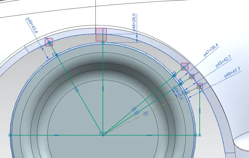
To satisfy the European standard, the design study is made as per standard and the following sketch is drawn.
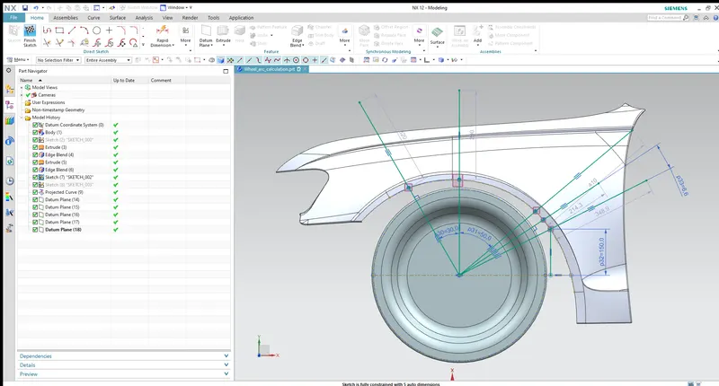
A centerline is drawn from the wheel center (SA).
1. From the wheel centerline, lines are drawn to an angle of 50 (SC) and 30 (SB) degree.
2. A line 150 mm from the horizontal wheel axis is intersected to the fender (SE).
3. A line is connected from the centerline to the above mentioned line (SE).
4. A symmetric line is drawn between SC and SE and connected to wheel centerline (SD)
5. The lines are projected to the top view.
6. The projected lines should be atleast 10mm inside the fender. (Wheel inside and fender outside).
The distance is measured from each section to the wheel front.
Section SA:
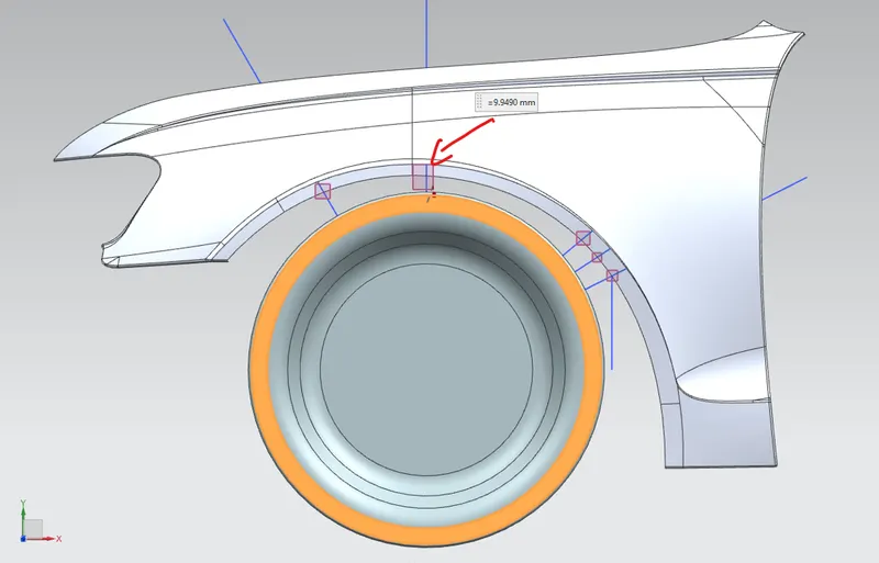
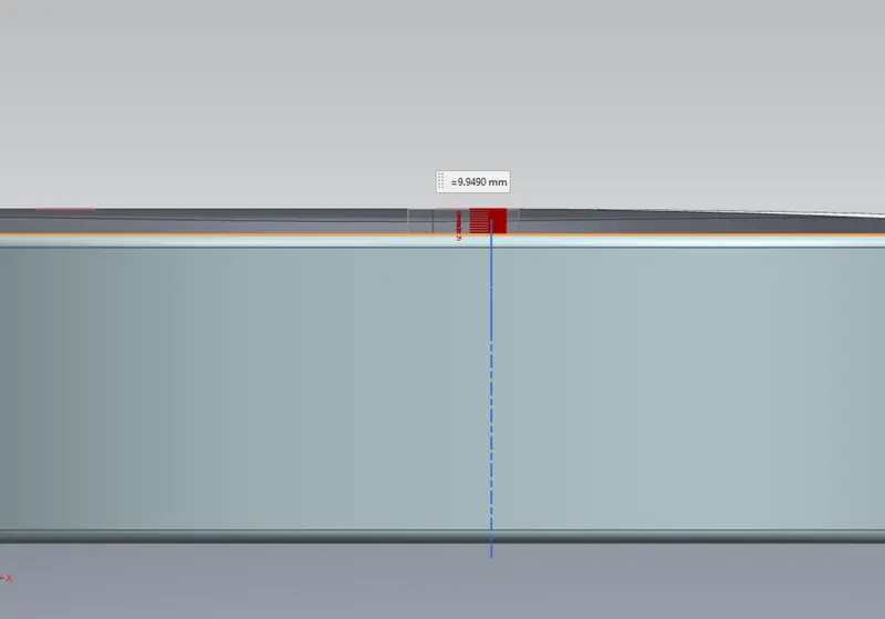
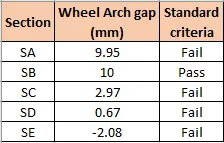
The distance is measured by projecting the sketch to the fender and a plane is created at the outermost point. The measured value is found to be 9.95 mm. The section doesn't match the standard design criteria.
Section SB:
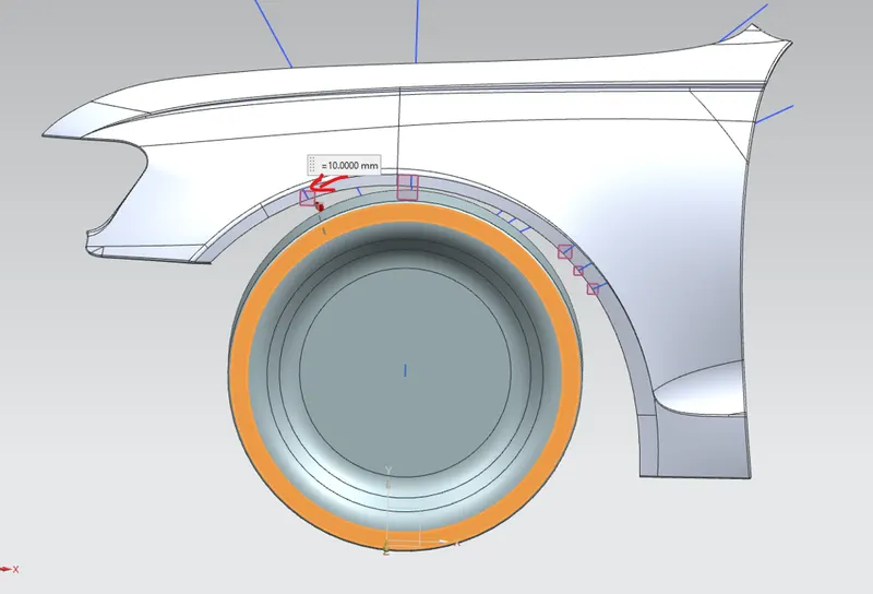
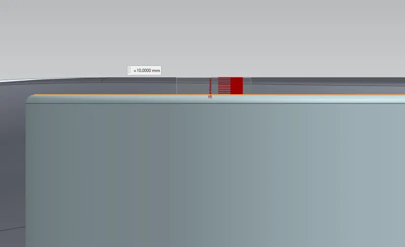
The measured value is found to be 10 mm. The section SB guides under the standard criteria.
Section SC:
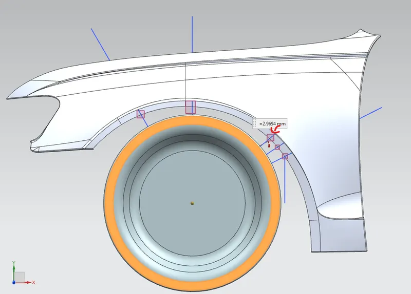
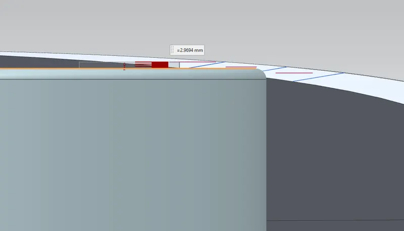
The measured value is found to be 2.97mm. The section doesn't match the standard design criteria.
Section SD:
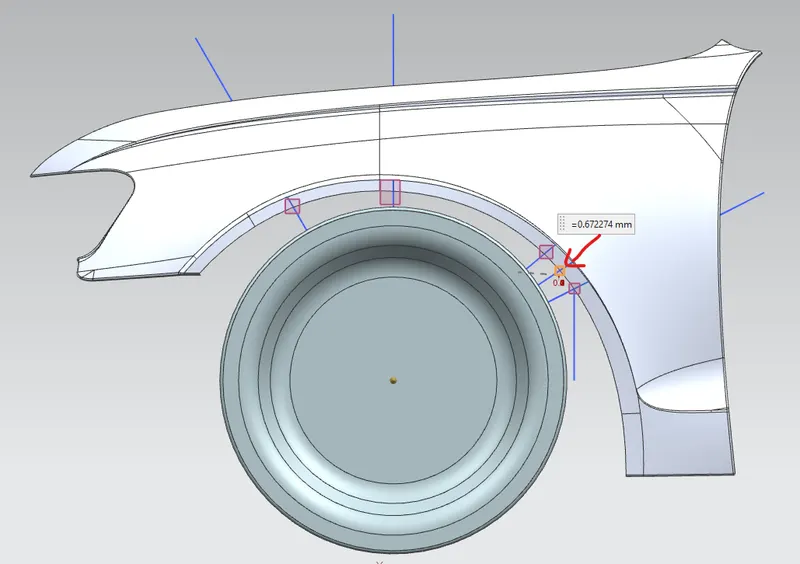
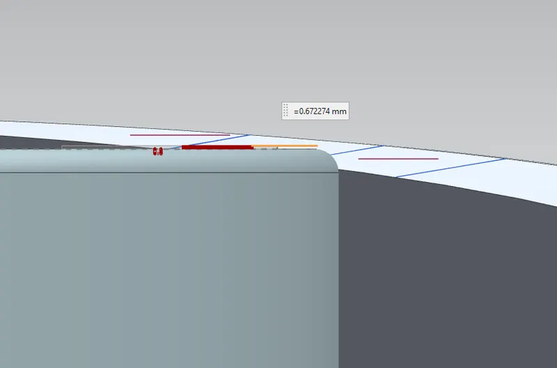
The measured value is found to be 0.67mm. The section doesn't match the standard design criteria.
Section SE:
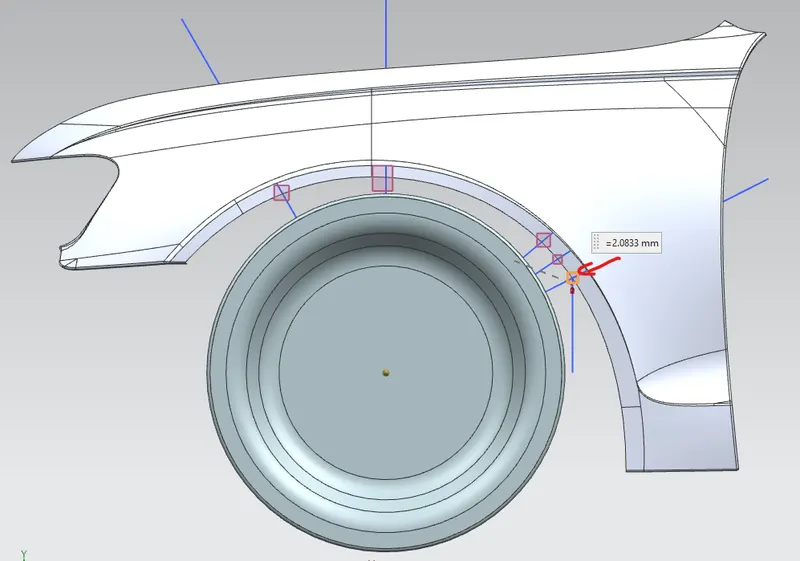
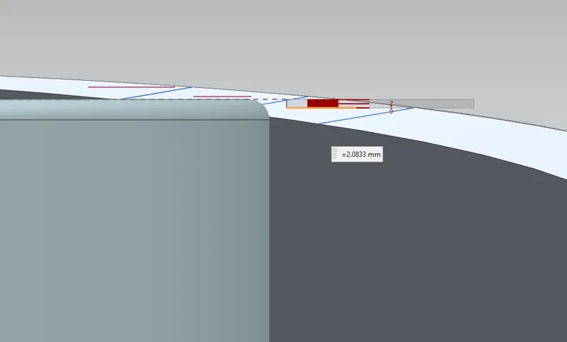
The measured value is found to be 2.08mm in negative direction. The section doesn't match the standard design criteria.
Conclusion:
The Fender is found to be misaligning with the European standard wheel arch practices at four sections of maintaining 10 mm gap. The styling surface needs to be updated to make it fall under standard guidelines.