Fender Design - Wheel Arch Challenge
FENDER DESIGN WHEEL ARCH
Fender:
Fender is the US English term for the part of an automobile (vehicle body) that frames a wheel well (Underside the fender).
It is primary design to prevent sand, stones, small debris, mud and other liquids to be thrown in to air by the tyre when in motion.
Fenders are basically present on the vehicle body to avoid injuries to pedestrians by this debris thrown in the air.
In narrow car body vehicles, tyres are exposed so to cover the top of the tyre fender is an exposed curve over the top of the tyre.
Meanwhile is wide body vehicles that covers tyre, fender forms wheel well surrounding the tyre, and it’s not visible from top of the car body.
Wheel Well / Wheel Arch:
The shaped part of the bodywork of the car or vehicle that allows wheel to be accessed and for the front wheels to be steered.
Wheel well are much larger than the diameter of the wheel as they do not tend to move with the suspension and that allows full movement
of the wheel in motion without touching the interior of the wheel. Sometimes fender skirts are designed to enclosing the outside edge of the
wheel well and stylized pontoon fenders for exposed fenders.
There are four fenders on the car body for all wheels defined as front and rear fender.
There are two types of fender Full fender and Half Fender.
Different countries have different design rules and regulations for vehicles, and the vehicle should qualify under their regulations.
For avoiding design alterations of same vehicle, it should be designed under considering all countries regulations if same vehicles are going
to be delivered in that countries and for that maximum values are taken for designing.
There are some countries Fender wheel arch regulations are discussed below.
- Japan Standard
- European Standard
- US standard
- Japan Standard:
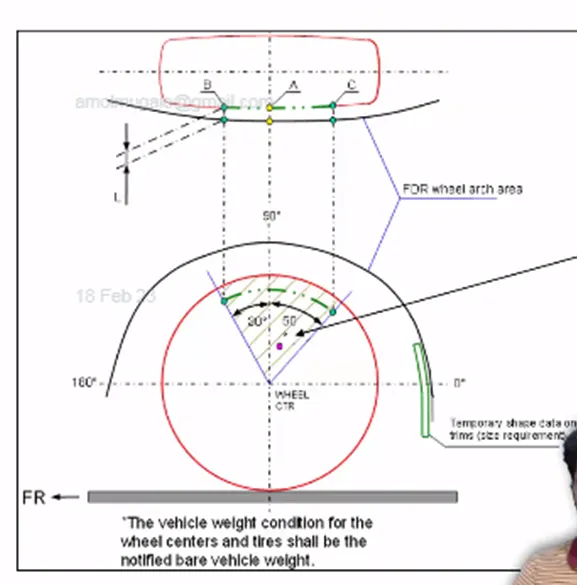
Above figure shows pictorial view of design considerations of fender wheel arch area under japan regulations.
Here, we have to measure clearance “L” of the tyre, hub, cap and fender in three different positions within area “K” and it should be above
5 mm at all three positions. Wheel guard requirement, the value of “a” should be more than 5 mm a line of 30° forward and 50° rearward
from the central vertical axis of the wheel.
- European Standard:
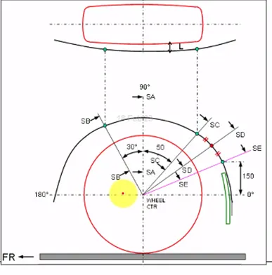
Above figure shows pictorial view of design considerations of fender wheel arch area under European regulations.
Here, we have to measure clearance “L” of the tyre, hub, cap and fender in different positions and it should be above 10 mm at all
positions to satisfy. Here, we have to make sections at SA-SA, SB-SB, SC-SC, SD-SD, SE-SE.
SA-SA is the 90° line from horizontal line and centre of the wheel.
SB-SB is drawn at 30° forward to 90° line and SC-SC line is drawn at 50° rearward to 90° line.
For SE-SE, point taken from horizontal line at 150 mm on fender line.
SD-SD is drawn at centre of SC and SE from wheel centre.
Wheel guard requirement, the value of “a” should be more than 5 mm a line of 30° forward and 50° rearward from the central
vertical axis of the wheel.
- US Standard:
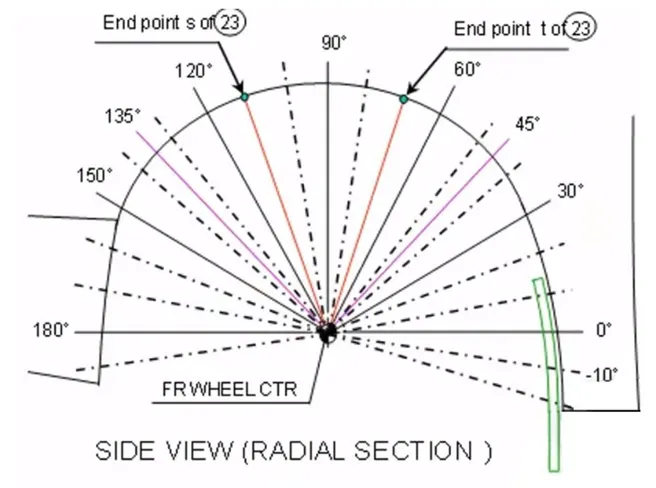
Above figure shows pictorial view of design considerations of fender wheel arch area under US regulations
Here, we have to measure clearance “L” of the tyre, hub, cap and fender in three different positions and it should be above 5 mm
at all positions. In US regulations we have to check details on all positions from -100° to 100° from central vertical axis of axis of
wheel and make the table for all value and all should be above 5 mm to satisfy.
Wheel guard requirement, the value of “a” should be more than 5 mm a line of 30° forward and 50° rearward from the central
vertical axis of the wheel.
Task: Calculate the wheel arch gap at required points and check whether the car possesses the European Standard.
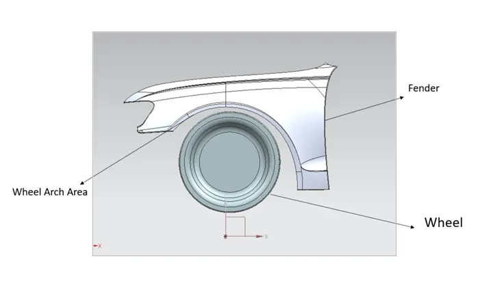
Sketch is drawn as per European standard on provided wheel and fender details and projected it on wheel arch at sections
SA, SB, SC, SD, SE to measure clearance “L” and wheel guard “a”.
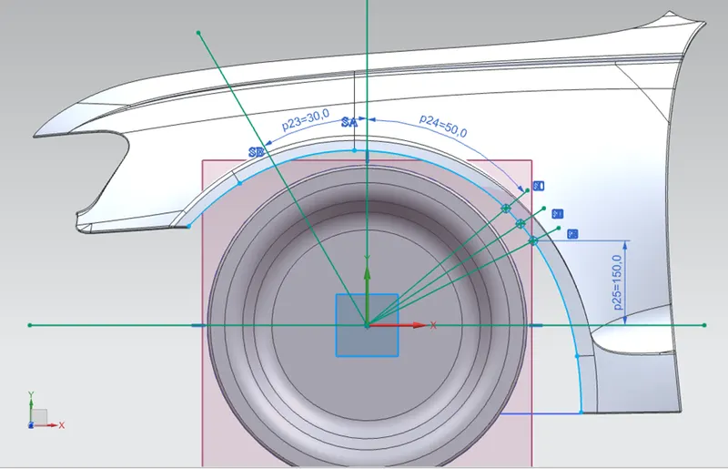
Values of clearance “L” at different sections SA, SB, SC, SD, SE are calculated as follows shown.
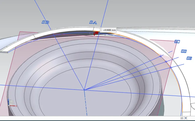
Value of L at SA is 9.9488 mm
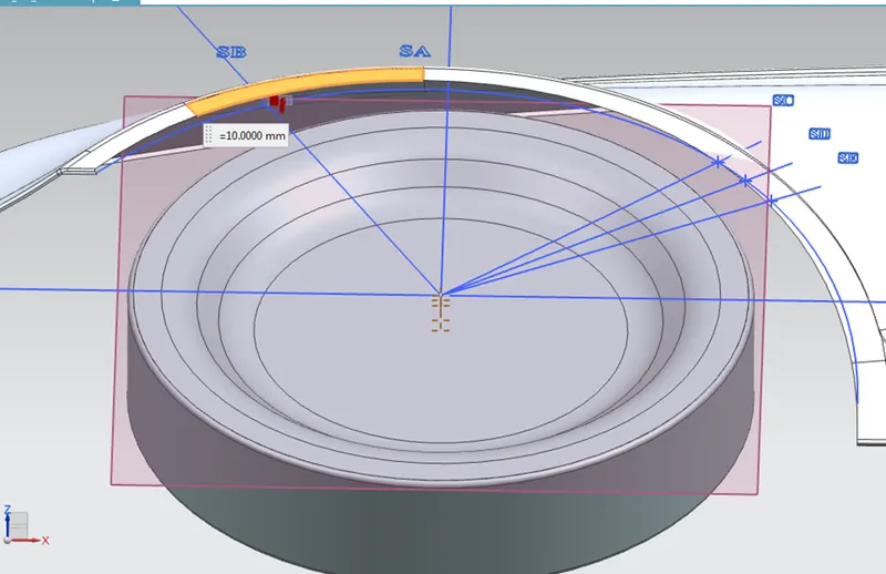
Value of L at SB is 10.00 mm
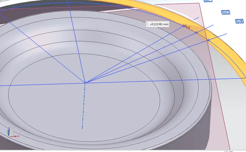
Value of L at SC is -0.1113mm
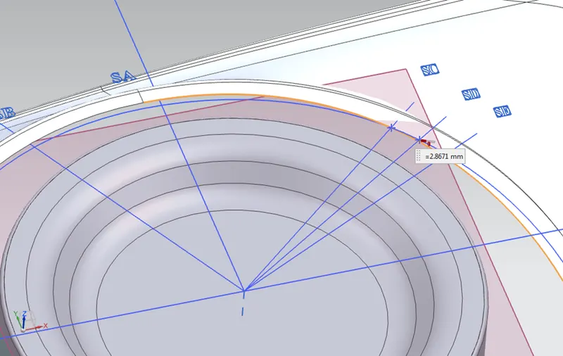
Value of L at SD -2.8671 mm
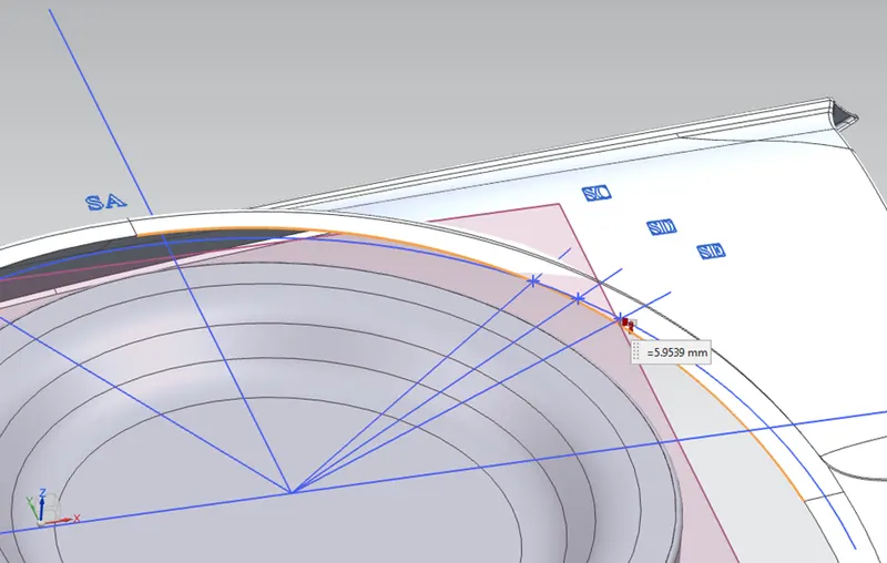
Value of L at SE is -5.9539 mm
All above values are tabulated below for checking of conditions.
|
SR NO |
SECTIONS |
CLEARANCE, L mm |
REMARK, >10 |
|
1 |
SA |
9.9488 |
< 10 , Fail |
|
2 |
SB |
10.000 |
= 10 , Pass |
|
3 |
SC |
-0.1113 |
< 10 , Fail |
|
4 |
SD |
-2.8671 |
< 10 , Fail |
|
5 |
SE |
-5.9539 |
< 10 , Fail |
Here, from above table it is observed that only on section is satisfying condition and 4 sections are failing
in design consideration of clearance L, so it should be modified as per conditions.
Now, we will check for wheel guard requirement “a”
We have to check value of “a” at two sections at SB and SC section which are 30° forward and 50° rearward from central
vertical axis of axis of the wheel.
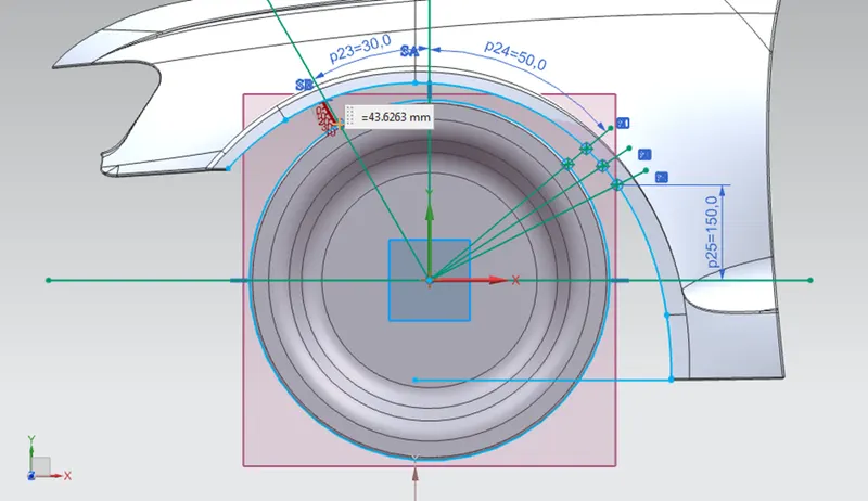
Here, value of “a” at section SB is 43.6263 mm
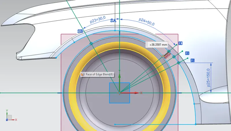
Here, value of “a” at section SB is 38.3597mm
|
Section |
Value of “a” , mm |
Remark, > 5 |
|
SB |
43.6263 |
> 5, Pass |
|
SC |
38.3597 |
>5 , Pass |
From above table, it is observed that value of "a" is satisfying the requirements as per European Standard.
Conclusion:
For above two values of Wheel Arch clearance is not satisfying European norms but value of Wheel guard “a” is satisfying.
As one of condition is not satisfying given car Fender does not possess the European standard.
Hence, we have to modify given fender as per European Standard for Clearance value, “L”.