Fender Design - Wheel Arch Challenge
'Fender Design - Wheel Arch Challenge'
Introduction:
Fender is the term for the part of an automobile,motorcycle or other vehicle body that frames a wheel well .Its primary purpose is to prevent sand, mud, rocks, liquids, and other road spray from being thrown into the air by the rotating tire.
Wheel Arch is the semi-circular part of the fender positioned above the wheel of the vehicle. The design of the wheel arch of the fender should be such that it must have some clearance while movement as well as it acts as a shield of wheel which also protects both passengers compartment and pedestarians from the projection of pebbles, water etc .The wheel arch area of the fender is usually designed as a protective cover over the tyre along its perimeter to stop any foreign particles.
Different Standards have to be followed by engineers while designing fender wheel arch like:
- US STANDARDS : Clearance L is to be checked with 5mm at all positions
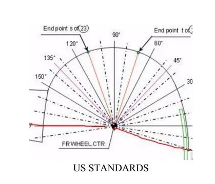
- JAPANESE STANDARDS : The value of L should be greater than 5mm
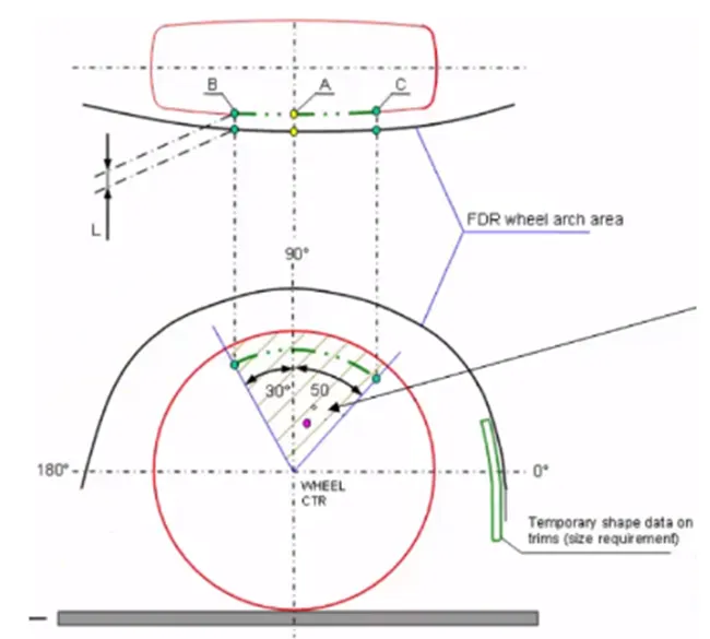
- EUROPEAN STANDARDS : The value of L should be 10mm
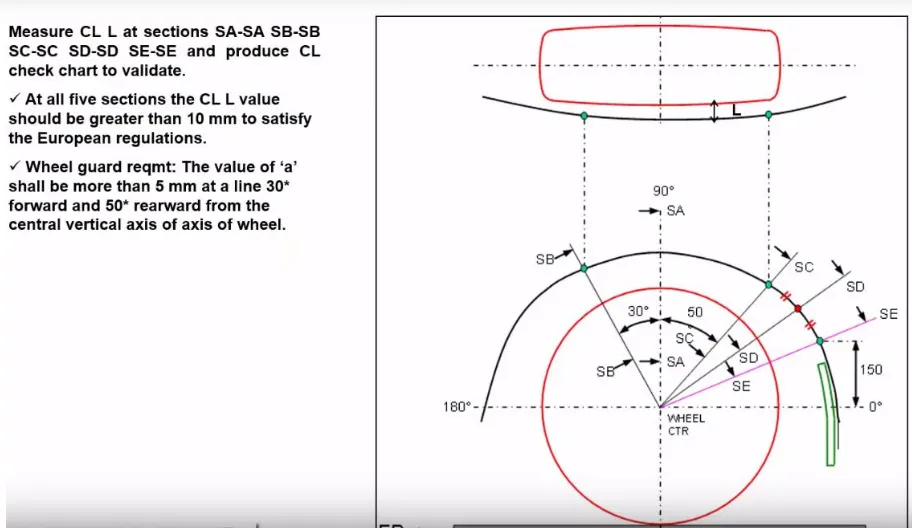
IN THIS PROJECT WE WILL FOLLOW AND TEST EUROPEAN STANDARD
STEPS TO Calculate the Wheel Arch gap at required points:
1)We will take datum plane on the extreme end bigger face on wheel with zero offset
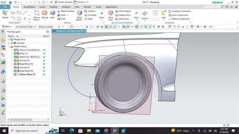
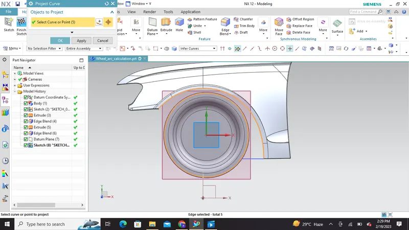
2) We will use project curve on our sketch selecting the extreme edge of fender and wheel
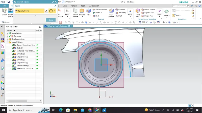
3) Then we will create a point using arc,ellipse,centre
4) We will create a vertical & horizontal line and convert it into reference
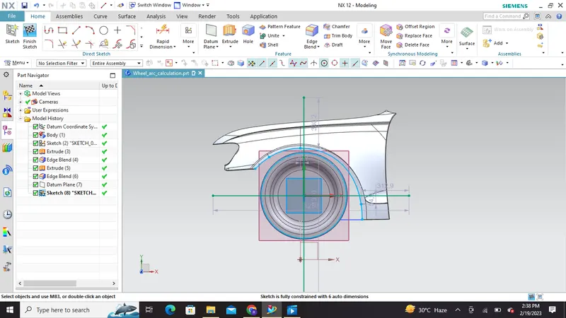
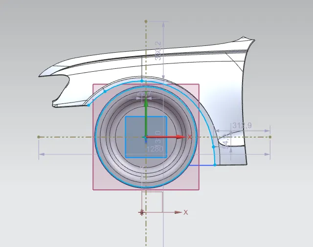
5) We will create a line of 30 degree on left side
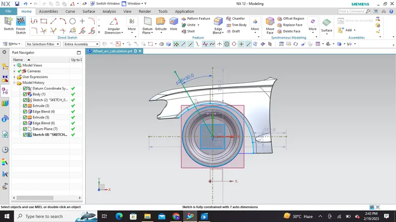
6) We will create another line of 50 degree from the vertical on the right side
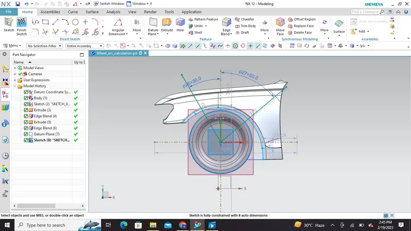
7) we will offset horizontal line to upward side at a distance of 150mm
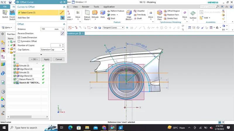
8) Then we will create points using interesection curve points
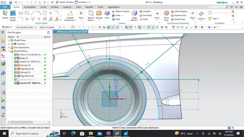
In the above sketch 4 points are created but according to european standards we need a 5th point as well
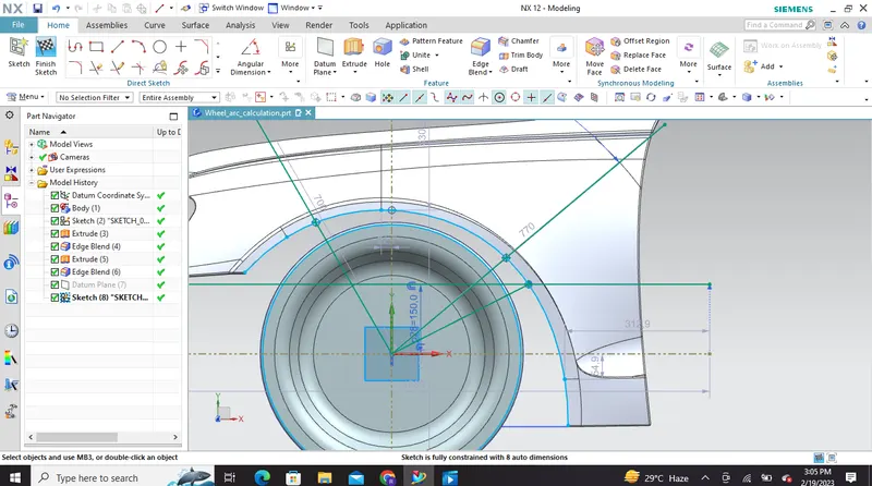
9) we will use derived lines command inorder to create a line parallel to another line midway between two parallel lines or a bisector between two non parallel lines
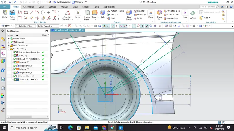
Finally using intersection point between derived line and edge of fender we will create the fifth point
10) As we can see on the below image that the points are not on the fender so we will project those points individually on fender and then calculate the clearance.
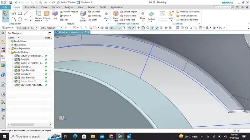
Using project curves we can see on the below image the points are now projected
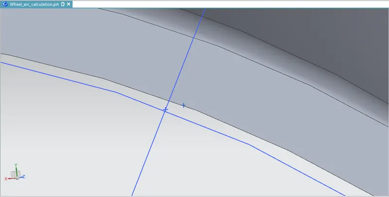
Measurements:
Measurement of 'L' value which is the clearance between wheel and fender wheel arc
1) SA
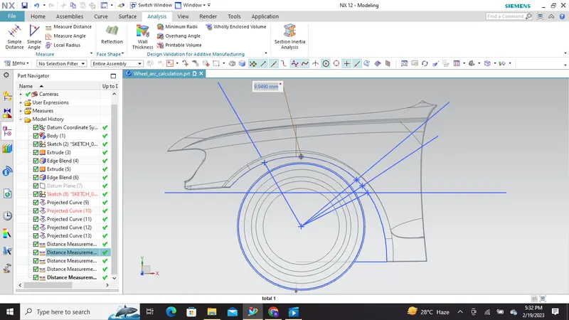
9.94mm
2) SB
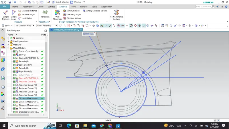
10mm
3) SC
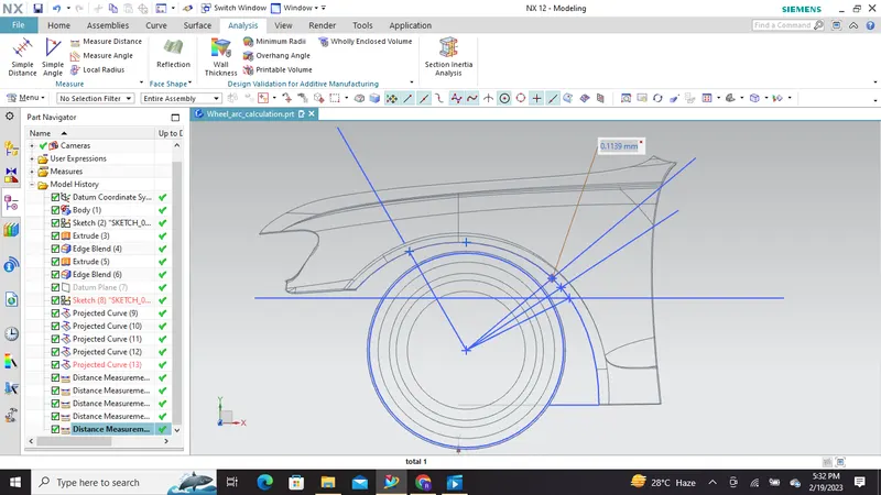
0.113mm
4) SD
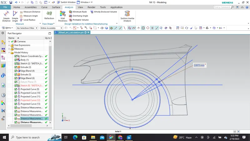
2.88mm
5) SE
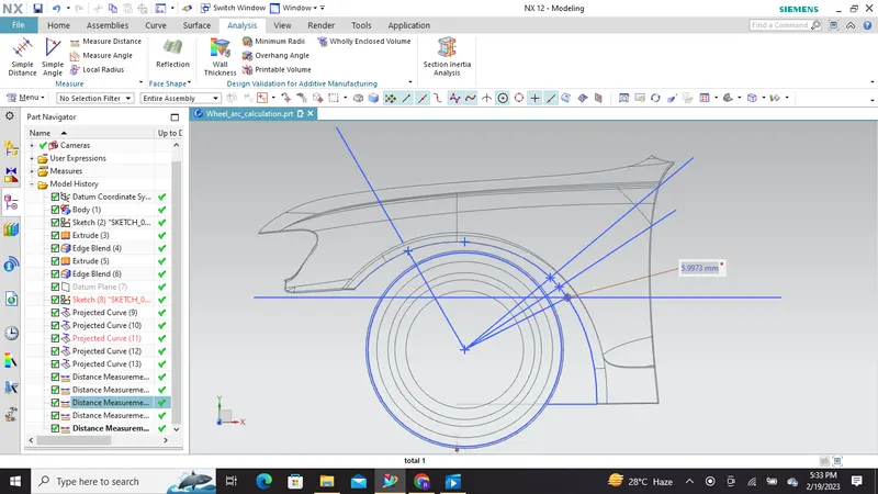
5.99mm
Measurement of 'a' value which is the clearance between fender arc and tyre
a value vertical measurement at 30 degree:
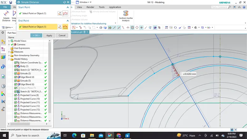
43.6 mm
a value vertical measurement at 50 degrees:
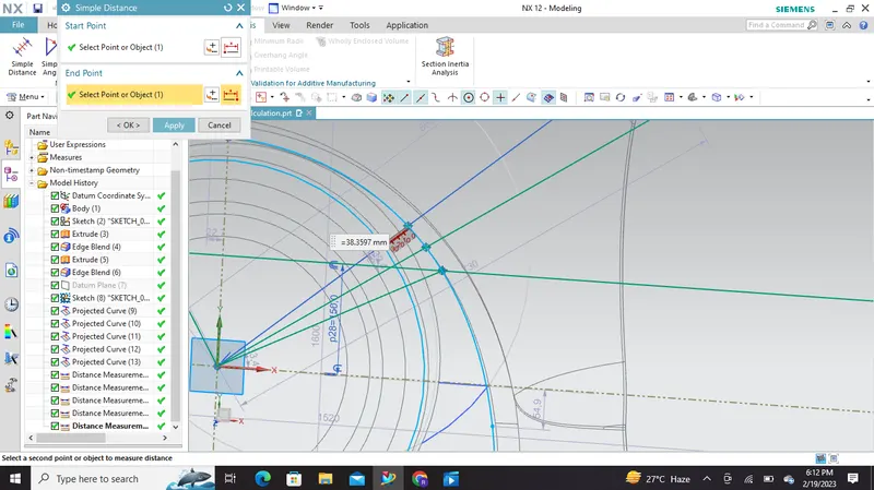
38.35mm
Results:
Clearance 'L' chart
| SECTION | MINIMUM CLEARANCE (MM) | MEASURED CLEARANCE (MM) | RESULT |
| SA | 10 | 9.94mm | FAIL |
| SB | 10 | 10mm | PASS |
| SC | 10 | -0.113mm | FAIL |
| SD | 10 | -2.88mm | FAIL |
| SE | 10 | -5.99mm | FAIL |
*Negative value means tyre is protruding outside the fender
Clearance 'a' chart
| SECTION | MINIMUM CLEARANCE(MM) | MEASURED CLEARANCE(MM) | RESULT |
| SB | 5 | 43.6 mm | PASS |
| SC | 5 | 38.35mm | PASS |
CONCLUSION :
Seeing the clearance values we can conclude that only section 'SB' is fulfilling the minimum 'L' clearance requirement according to European standards and all other section failed, Furthermore we can also see points at section SC,SD & SE are outside the fender which is not allowable so alterations must be made in the fender in order to meet the standard requirement. Thus this fender model failed to satisfy the european standards.