Fender Design Challenge
FENDER
Objective:
The main objective of this challenge is to create a fender along with the mounting flanges from the input data & the given master section details using Catia V5.
Introduction:
Fender is the part of an automobile, motorcycle or other vehicle body, installed over the wheel, which frames a wheel well. Its primary purpose is to prevent the road debris from being thrown by the rotating tyre either inwards into the vehicle body or outwards to the surrounding causing damage.
Fender panel are located on the sides of each front wheel. These panels typically cover the sides of the headlights to the hinge of the driver and passenger doors on the A-pillar. They run vertically from the hood to the wheel well.
Types of Fender:
- Full Bumper type.
- Half Bumper type.
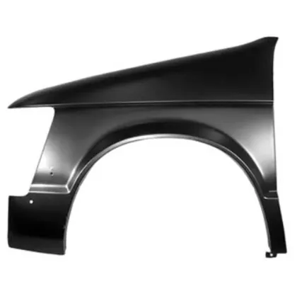
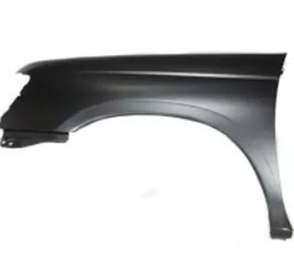
- Presently we are using half bumper type, the reason for choosing the half bumper type is that when we choose the full bumper type, the blank used for creating it is very large and also has the lot of wastage. But in the case of the half bumper type we have the possibility to reduce the scrap.
- In half bumper we reduce the usage of the steel material and uses the lots of plastic on the bumper which in term decreases the cars weight and increases the performance.
Design Consideration:
Given data and design consideration are as follows:
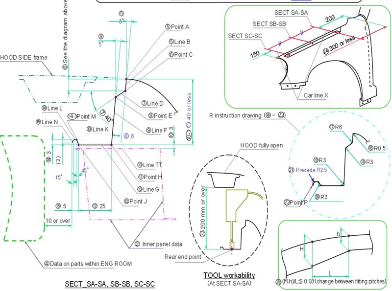
The fender is expected to be firmly attached to the body of the vehicle. Hence, multiple mounting points are provided for the fender to be fastened to the body. Flanges are designed on the fender at the respective mounting points for the purpose of fastening.
- Drip
- Bumper
- Baffle
- Sill
- Body or A-pillar
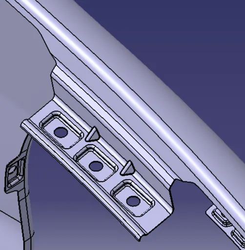
- Drip: The region where the front fender is attached to the engine compartment of the vehicle. This is the most important mounting regions as the maximum area of support can be achieved. There are certain design parameters to be followed for the Drip area flange for proper mounting of the fender and to avoid intersection with components inside the engine compartment. As the drip area flange is usually long ribs are provided for additional stiffness.
2.Bumper: The region where the front fender is attached to the front bumper of the vehicle.
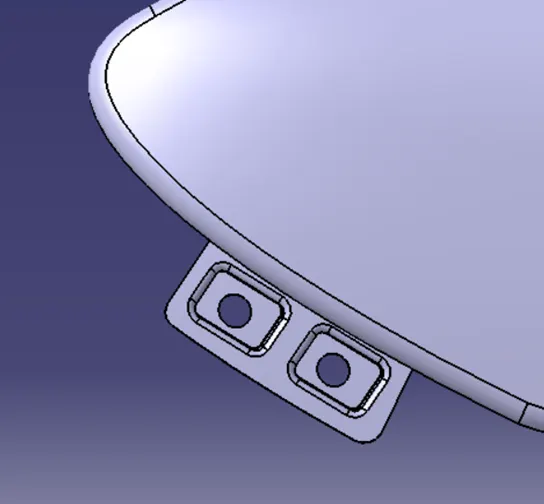
3. Baffle: The region where the rubber mudguard are mounted on the inner side of the fender arch over the tyre, it protects the car engine compartment and pedestrians from causing injuries from chip out debris on the road when the car is in motion.
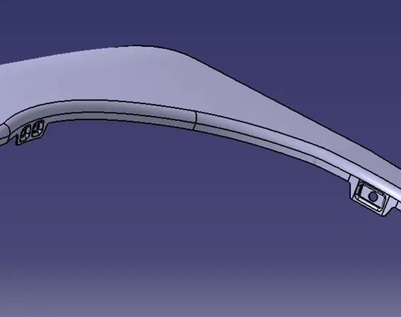
4. Sill: The region where the front fender is attached to the bottom part of the vehicle body.
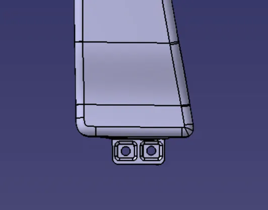
- A-pillar or body: The region where the fender is attached to the A-pillar of the vehicle body, sometimes instead of the A-pillar, the front fender is attached on the cowl region where the ORVM is fixed.
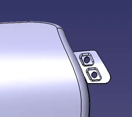
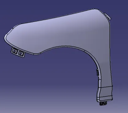
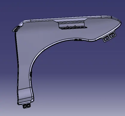
Fender Images:
Manufacturing process employed in Fender:
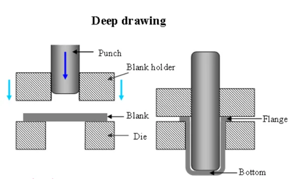
- Deep Drawing: it is a sheet metal forming process where sheet metal blank is converted into a desired shape by pressing the sheet with punch into die.
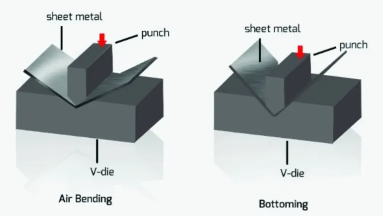
- Bending: sheet metal is deformed into u,v or channel shape. The material is subjected to both tensile and compressive force. Usually, the sheet metal spring back to regain its original shape due to residual force after the removal of the deforming forces. Spring effect depends on the material and operation performed.
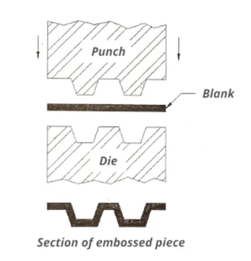
- Embossing: In which impressions are made on the sheet metal blank such that the thickness remains uniform throughout the sheet even after the embossing has been done.
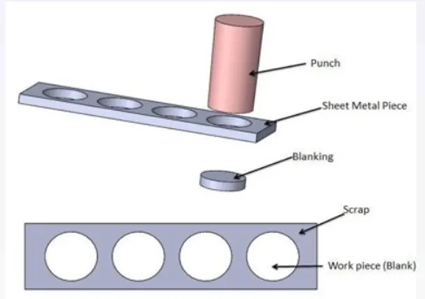
- Blanking: Sheet metals are kept on a die and is sheared or pierced by a punch of desired shape. Punched out part is called blank and no further machining requires.
Conclusion:
Hence, the fender is designed and developed from the given surface data and according to the design data given.