Fender Design Challenge
AIM:
- Design and model the front fender by providing skin data as per the design parameters.
INTRODUCTION:
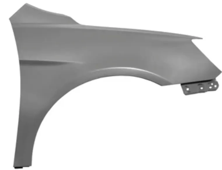
- Fender is an automobile sheet metal component.
- Fender is the curved part of the car’s body that sits on the top of the wheels and holds them in place.
- Fender on the car are panels that extend from the front bumper to the car’s doors.
- The car’s fender enhances the overall elegant look of the car.
PURPOSE OF FENDER:
- The primary purpose is to prevent sand, mud, rocks, liquids, and another road spray from being thrown into the air by the rotating tire.
- Fender provides safety to the drivers and passengers at the time of accidents or collisions.
- They are manufactured in a way to provide bend during front and side collisions.
- A car’s fenders are designed to avoid wind resistance and make your car aerodynamically.
- By the improvement of aerodynamic shape vehicle reducing air turbulence and air resistance.
- An aerodynamic-shaped vehicle having greater stability.
- A system completely enclosing all wheels of the vehicle making it more aerodynamic.
TYPES OF FENDER:
1. FULL TYPE FENDER
2. HALF-TYPE FENDER
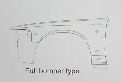
1. FULL TYPE FENDER:
- This type of fender is not commonly used because this design is more scrap during manufacturing.
- This type of manufacturing of fender makes the more wastages.
- It consumes more cost to manufacture.
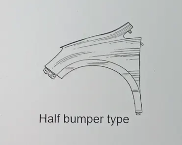
2. HALF TYPE FENDER:
- This type of fender is most commonly used.
- The cons of full type fender are satisfied in the design.
- The blank area of wastage while producing the part is drastically reduced by scrap management.
The fender comprising
- Drip area mounting
- Sill mounting
- Bumper mounting
- A-Pillar mounting
- Baffle splash mounting
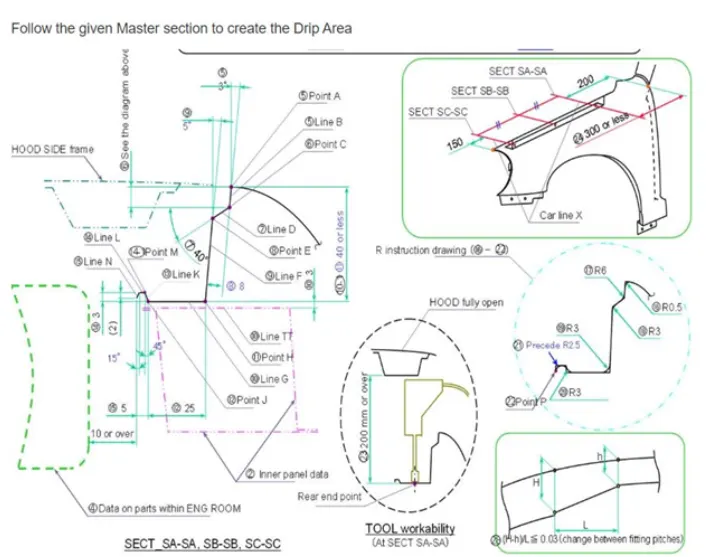
DRIP AREA MOUNTING:
- It is the critical mounting area located inside the engine component.
- It has been designed according to the master section provided and an optimal opening angle of 3 degrees is maintained to make it look well assembled from the outside. When assembled the fender is straight vertically it also disturbs when opening and closing the hood.
- To design the drip area mounting different constraints should be used.
- The minimum clearance of 150 mm from the headlamp and cowl part is maintained. The vertical distance of the drip mounting is maintained at less than 60 mm to avoid the spring back effect.
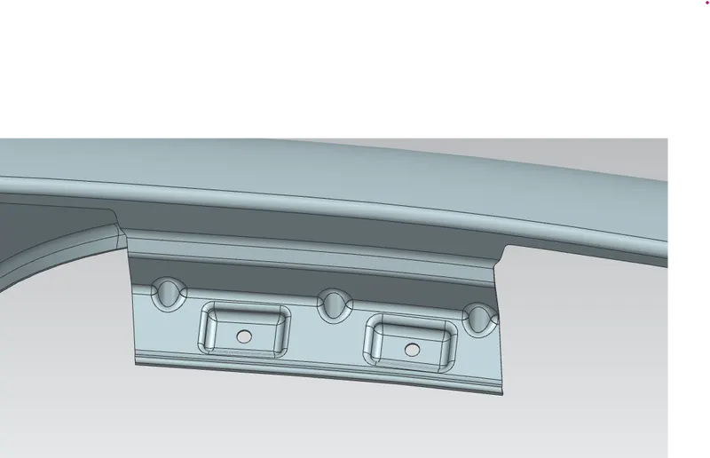
- Drip area is mounted to engine compartments by weld nuts.
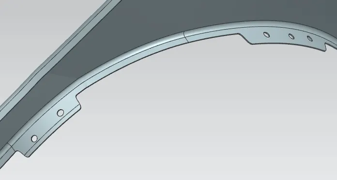
- Ribs are applied at the drip area mounting to maintain the stiffness.
- The clearance of 10 mm should be maintained between the end of the drip area and the engine compartment.
- To sketch the circle on the mounting area to create holes 5 mm diameter of constraint should be maintained at all mounting positions.
SILL MOUNTING:
- The sill mounting region is located near the left bottom edge of the front doors.
- It is connected with the bottom area of the front doors to enclose the body panel.
- The sill area of the fender is mounted with the left bottom area of front doors through fasteners.
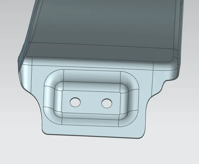
BUMPER MOUNTING:
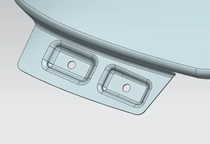
- Bumper mounting area has been designed at the top left edge of the fender.
- The bumper automobile part has connected at the bumper mounting area of the fender through the fasteners.
A-PILLAR MOUNTING:
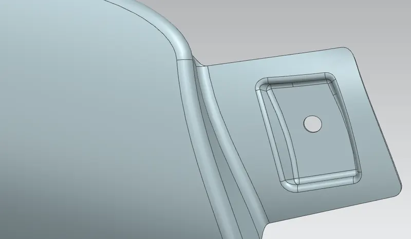
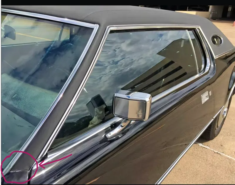
- The A-Pillar is the structural upright that partially frames the windshield.
- The A-Pillar is joined across the top of the windshield by a header rail.
- The A-Pillar mountings are designed at the top right corner to connect the top body frame of the car.
BAFFLE SPLASH MOUNTING:
- The wheel arc mounting hole is provided at the wheel arc area of the fender.
- The wheel arc baffle is added to absorb noise from the engine compartment.
MANUFACTURING PROCESS OF FENDER:
Preliminary preparation of sheet metal:
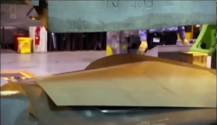
- The manufacturing process of fender includes the following steps that firstly unfolding and shearing are carried out on a plate, where proper cold roll specification is selected at first, a cold roll is unfolded, and then the unfolded cold roll is sheared to an iron plate of the corresponding according to production material specifications.
STAMPING DIE PRESS OPERATION:
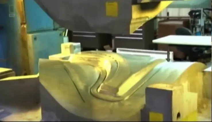
- Oil pressing and punching are carried out where the iron plate is extended first.
- The side shearing and punching are conducted on the iron plate.
- Folding and shaping are carried out on an iron plate and finally shaping is carried out on the iron plate.
MACHINING:
- Finally small extra parts are machined.
FENDER IMAGES:


CONCLUSION:
- Designed and modeled the front fender as per the design parameters through NX CAD.