Fender Design Challenge
AIM:
To design the Front fender from the given skin data by following the design rules and Master section.
PROCEDURE:
Fender
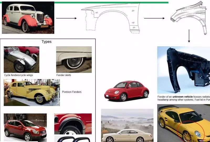
- Fender is a protective covering of an automobile which covers the wheel and avoids the road spray from the wheel towards air, pedestrian, and other vehicles.
- For designing a fender we need to follow the design rules, these rules are explained in detail below.
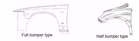
- Basically there are two types of fender they are Full bumper type and half bumper type. Nowadays most of the cars are having half bumper only for cost savings. Old vehicles are having full bumper type. It is shown in the below image.
Considerations for fender design
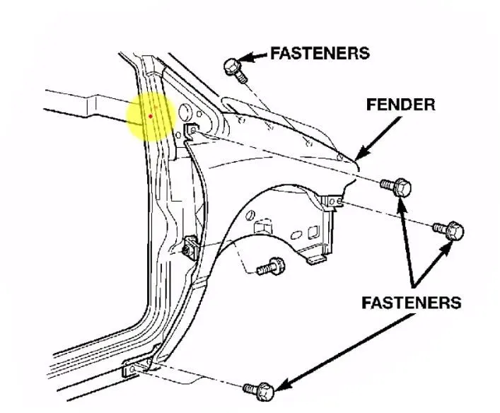
- For mounting point of view we always have 5 mounting points in a Fender they are
- Body
- A pillar
- Sill
- Cowl
- Drip
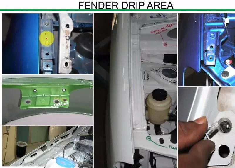
- From the above design requirements, the Drip area is the most important area for designing the fender. For fender drip area we are having various regulations to design for the pedestrian safety and for easy fixation of the fender with the engine compartment of the vehicle. It is shown below.
- The fender drip area always should have the following clearances for the ,ounting purposes. From the viper motor mounting region the fender should atleast have 200mm clearance then only the mounting of the fender by the use of the power tools also will be easy. It is shown below.
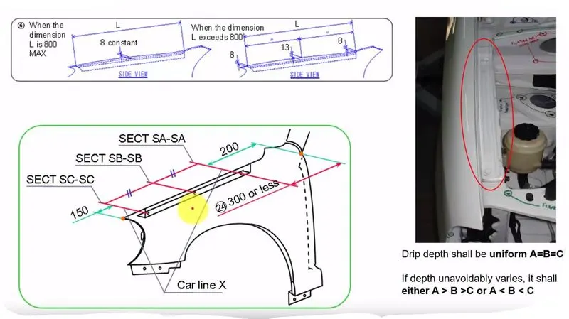
- The 200mm gap maintained from the one end of the fender will give the good tool workability for the fender while assembling it with the help of power tools. It is shown below.
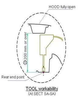
In the above image the rear end point specifies the end point of the fender drip area.
- And the drip area should maintain atleast 150mm of gap from the head light mounting area. To make the clearance for the head light mounting provisions, and the drip sholud have atleast 10mm of clearance for not making any damage to the other inside components while installing the fender to the vehicle.
- Another design regulation is we should follow the master section of the fender provided, this master section is shown below and their purposes are given in the below image.
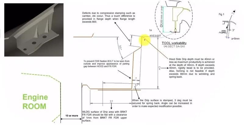
- Here we are following the inclination angle of 3 degree for making the flange to hide the inside bolting and fixation area when customer is seeing from the side of the car. And the flange should have a little opening angle from the fender surface to have a good manufacturability.
- The maximum length of the fender should not go beyond 60mm, if it goes beyon 60mm there will be some spring back effect, this will cause the fender drip area to deform its posistion after pressing or stamping process. So here in this design it is kept for 43mm.
- And the 10mm clearance gap is provided for the flange to the other components in the surronding of the fender in engine compartment area to avoid any collisions while assembling the components.
Side reference line
- Another important safety factor while designing the fender is side reference line. The can be explained from the below image,
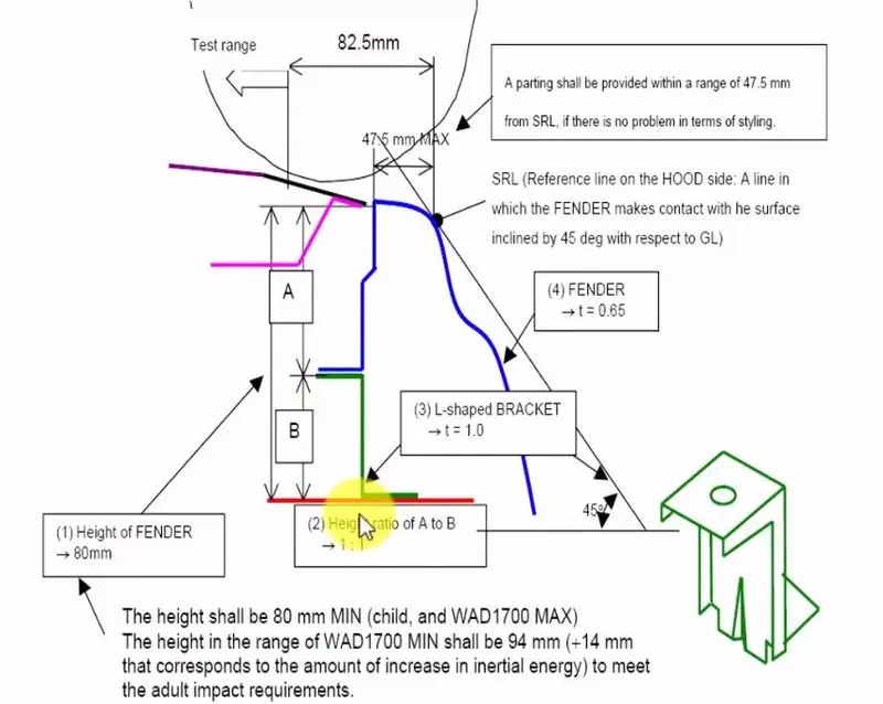
- In the above image the side reference line is shown, the side reference line is the line drawn for 45 degree from the ground level touching it to the fender.
- For the pedestrian safety the distace between the side reference line touching point with the fender to the edge of the fender should be lower than 47.5mm, the maximum value is 47.5mm it ahould not go above it, for the pedestrian and wrap around distance this value is maintained.
- If the skin data of the fender from the studio is not having this value we need to inform the styling team to make the change in the class A surface.
Fender wheel arch requirements
- There is some regulations followed for the fender wheel arch calculations if the class A skin of that wheel arch doesn't fulfill the requirements that fender sking data should be altered.
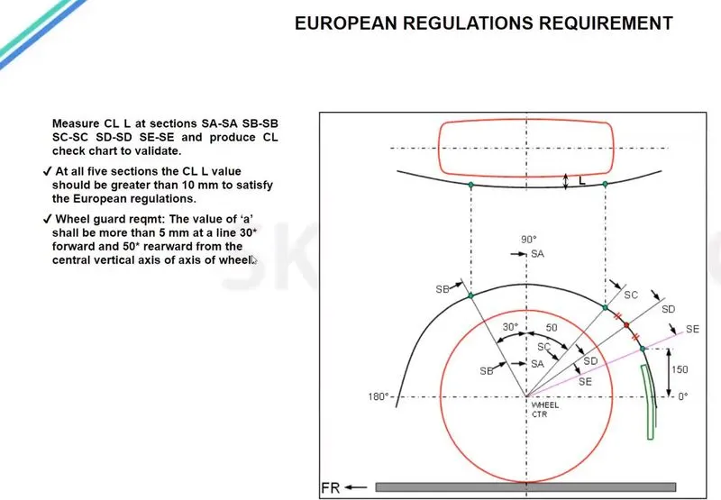
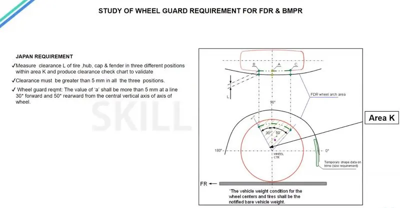
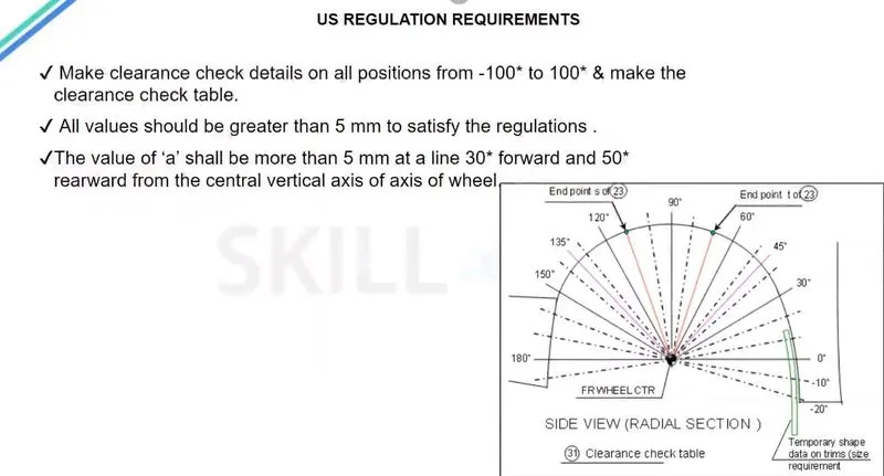
- There are various countries are following various regulations according to their road condition, here we can see for three countries such as Europe, Japan, US
- For European regulations the fender should pass the below requirements.
- For Japan regulations the fender should follow the below requirements
- For US road conditions the fender should follow the below rquirements.
Master section for fender
- The below image shows the master section for the fender design,
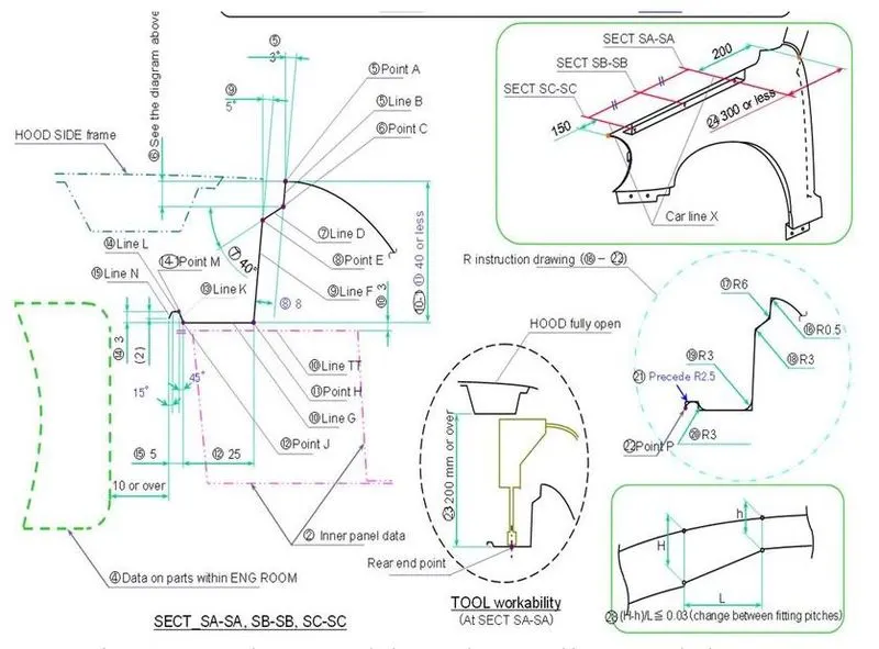
According to the above master section the fender will be designed here input class A is given it is shown below.
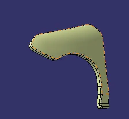
This class A surface is splitted according to the drip area and flange requirement areas.
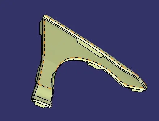
This split is done according to the mounting requirements, they are Body side, A-Pillar side, Cowl, Drip area, Baffle area.
Then we have to strengthen the part according to the area, we have to give reinforcement for the Drip area and other mounting areas, and we have to strengthen the mounting area by providing the embosses on the mounting areas of the flanges.
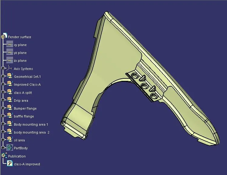
We can use the dart feature on the Biw templates tab to provide the stiffness for the part, by the same way we need to add the stifness in the required areas.
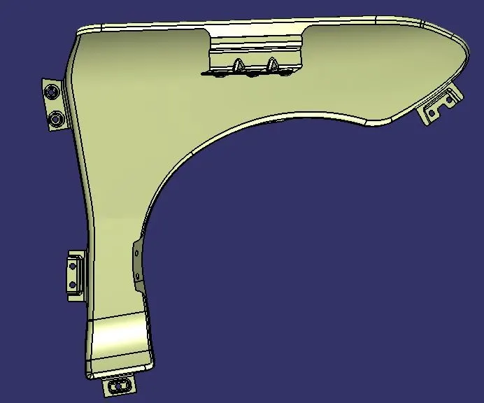
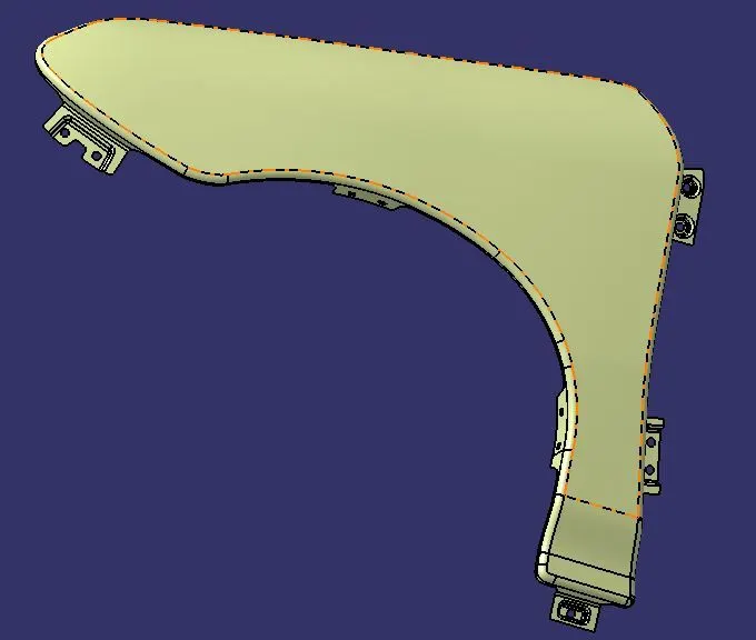
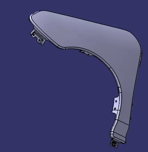
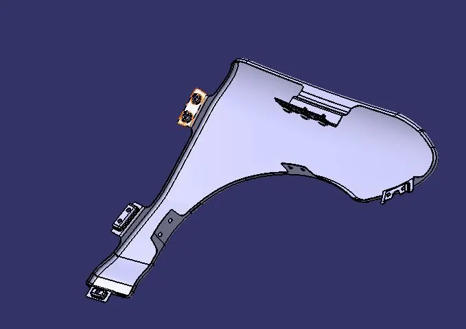
After completing the flanges and all things we have to add thickness to the part. The part thickness is 0.75mm this can be done with the help of thicken command.
Conclusion
Thus the Fender is designed from the input skin data(class-A) and thickness value is applied to that by following the design rules and master section.