Fender Design Challenge
REPORT: FENDER DESIGN AND DEVELOPMENT USING UG NX
AIM: To design the fender part of BIW and create support features to join with the respective BIW panel.
INTRODUCTION :
A fender is an automotive part that covers the Wheels from the upper side. Fender also protects against the entry of hazardous materials into engine compartments like stones, mud, sand, dust particles, and other liquid material over the road. These materials stick with tires while driving and try to enter the engine room. So that fender also protects the pedestrian from attacking these materials during running conditions.
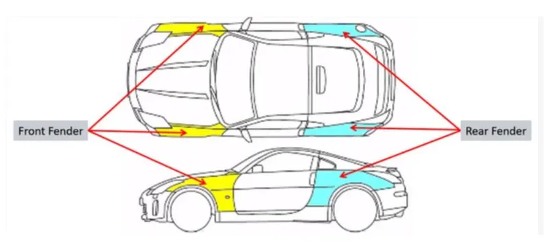
Generally, cars have four fenders on each wheel, two on the front side and the remaining on the rear side.
Fender views on the car:
TYPES OF A FENDER-
- Full Bumper type
- Half bumper type
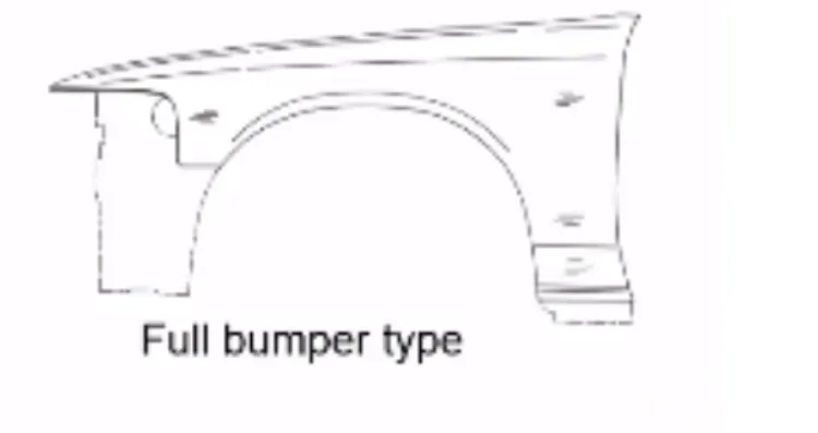
1. Full bumper type :
This type of fender is not used nowadays, Because of its large requirement of sheet material. It also covers the wheel well properly but due to the manufacturing process and production cost as well as wastage of material is more so it is not preferred.
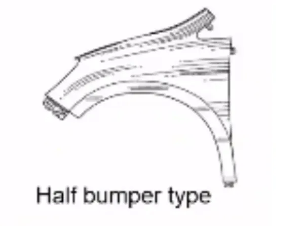
2. Half bumper type :
The secondary option for a full bumper is to be a Half bumper type. By using the half bumper we reduce a scrap of material as well minimize the cost of production and also reduce the weight of the car. Along with the half bumper, we use the plastic parts as a supportive member. So we can increase the performance of the car.
Fender mount region on BIW:
- A-pillar Mount
- Body mount
- Sill mount
- Bumper mount
- Drip mounting
1. Body mounting :
Some of the portions of the fender part are attached with BIW body frame where fender as well door are attached with the help of screw, bolts, etc. generally M5 bolts are used to attach fender. On the body mounting region, most of the parts are attached because it is part of the base frame structure and provides better supportive strength to assembled components.
2. Sill mounting area :
The sill mounting area is nothing but it is the floor area of the car where all BIW frame is structured. To provide extra strength from the floor region some portions of the fender have been joined with the help of fasteners. For face-to-face attachments, the designer needs to provide plane shape on assembled parts. Generally, M5 fasteners with flat heads are used.
3. Bumper mounting region :
The baffle mounting is a rubber-type material clipped to an inner surface of the fender. The baffle is attached with the help of plastic push clips. The primary reason to use the baffle on the fender is to protect the engine from the hitting of mud particles, sands, stones, rocks, and other liquid material during the running motion of the car.
The front-most region of the car fender needs to be assembled or to have strong support so that the Fender is fastened with the bumper with creating a supportive structure on both bumper and fender. As the bumper is mounted on the chassis and engine compartment region so it gives strong support to the fender.
4. Drip mount region :
The drip mount region is found on the engine compartment where the engine and its supportive brackets are arrested on the chassis. As the engine housing provides stronger support some portions of the fender are attached. Before the attaching fender to the engine, the housing designer needs to check the available space and regarding it, a designer creates some extra engineering features on the fender's stylish surface. Also, another importance in the creation of the drip region is to hide the inside look of the engine assembly which is not aesthetically good.
Sometimes BIW designers need to follow the drip master section to study and analyze available space for proper attachment of the fender. Generally, M5 flat head bolts are used to assemble the fender with the engine compartment.
MATERIAL SPECIFICATION : The material used in Fender design are as follows-
- Drawing Steel
- Deep drawing steel
- Dent resistance steel: Bake hardened steel
GIVEN DATA FOR DRIP REGION -
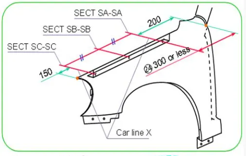
The figure shows that Specification data to provide some allowances before designing the drip area on the fender.
In the front end of the fender, the space is provided near about 150 mm because of the proper available space for the headlamp of the car.
At the rear end of the fender, we need to provide some gap of approximately or less than 300 mm for the cowl space. The cowl space is provided to carry the wiper motor and its instrument arrangements.
DRIP DESIGN SPECIFICATIONS :
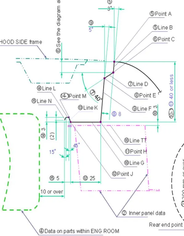
- The 3-degree draft is provided on the upper surface of the fender for easy drawing operation with a depth of 9mm. This is because to perform another draw operation on the fender surface.
- Generally this double draw operation is preferred to hide the inside view of the engine compartment.
- The flange height from the top of the fender does not exceed 40 mm, because most of the tool does not produce flange depth above 40 mm and also gives SPRING-BACK effect.
- The flat portion of the fender should be less than 30 mm to propper weld nuts as well as sufficient flat space for supportive brackets which are welded or fastened to the fender's flat surface.
- On the extra portion of the fender, perform the draw operation to provide strength and maintain the min. 10 mm distance from the end of the engine.
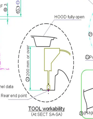
Tool workability: The figure shows the hood is in an open condition and the machine is entered into the engine compartment to fasten the fender drip with engine supportive brackets. So that too easy movement of walnut machine BIW designer needs to leave space of 200 mm. at open condition.
DESIGN PROCESS USING UG NX :
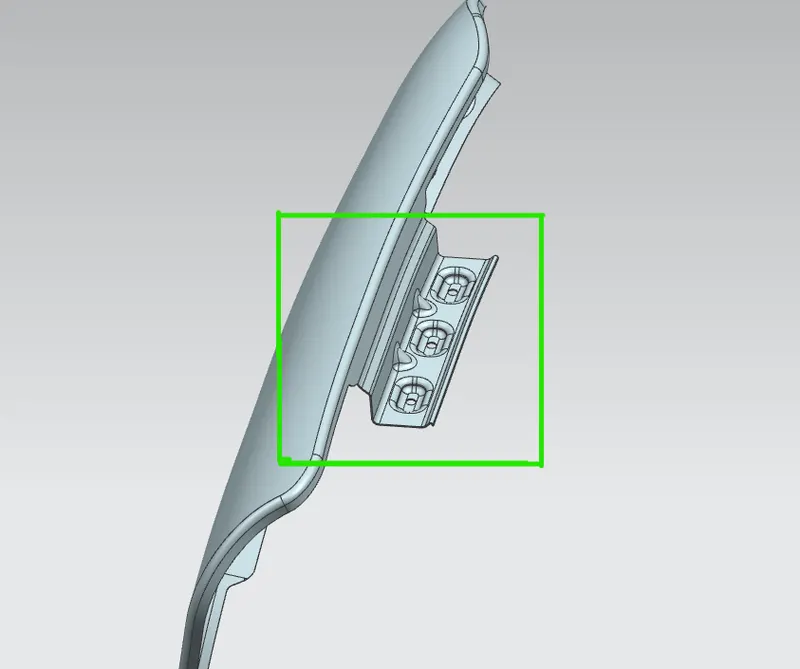
1. DRIP MOUNTING AREA -
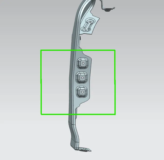
2. BODY MOUNTING AREA -
3. SILL MOUNT AREA -
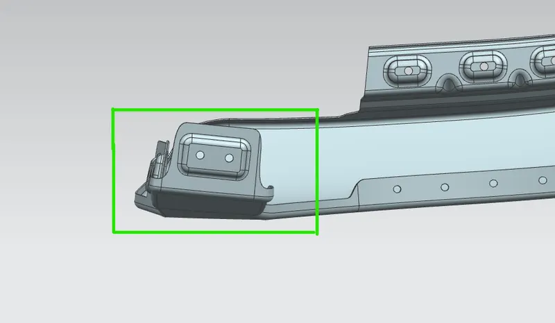
4. BUMPER MOUNT AREA-
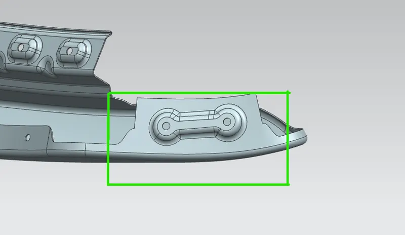
5. BAFFLE MOUNT AREA-
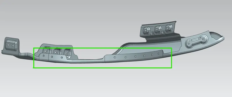
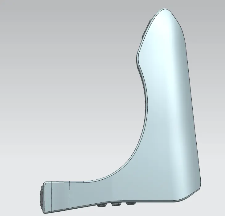
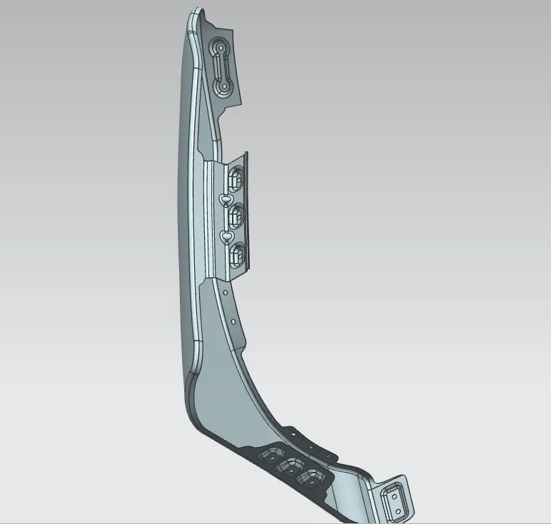
Fender's different orientation view-
1. Front view :
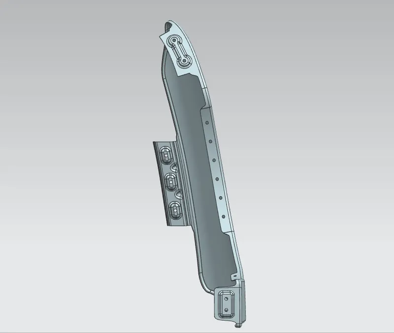
2. Side view :
3. ISO. view :
CONCLUSION :
- Understand about drip area and its development.
- Learning about the different mounting regions for the fender.
- Understand the importance of baffle concerning the fender.
- Learn to design and develop offender, and mounting regions with the help of UG NX software.