Fender Design Challenge
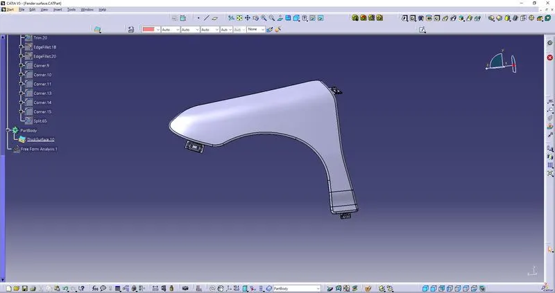
Aim: To design a front fender from the given skin data and the master section provided with Drip mounting, A-pillar, Sill, Bumper, C mounting and Splash mountings.
Theory:
Fender:
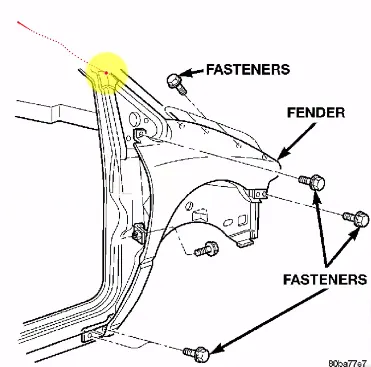
The below is the image of a Front Fender and the same is discussed below.
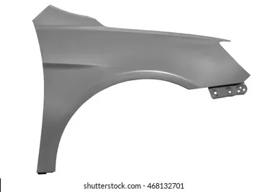
Front Fender is one of the side closing component for the engine compartment.Its main role is to avoid chipping of stone, dustparticles,liquids etc inside the engine compartment. During motion the wheels try to pick up some mud particles, stone particle etc and throws it inside the car region.Therefore, fender helps to prevent these particle to damage the engine compartment and also fender will have a plastic material on the arch area called wheel arch lining.
The fender's openings for the wheel tend to be much larger than the diameter of the tire because they do not move with the tire suspension and consequently must be large enough to allow the full range of tire motion on the suspension without touching the interior of the wheel well.
Types of Fender:
1) Full Bumper Type Front Fender:
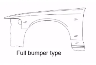
Here the blank which is used to create the full bumper is really big and wastage or scrap is more.
2) Half Bumper Type Front Fender:
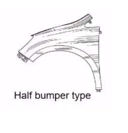
Here we have a high possibility of reducing the scrap which means by slightly increasing the blank size we can produce to half bumper type.
Hence almot most automobile company uses half bumper type which gives better fender at a cheaper prize.
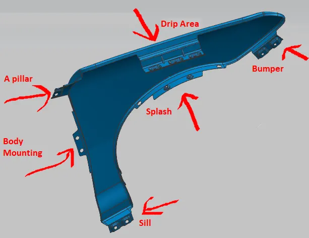
Mounting: Fender are basically mounted on 5 important regions
- A-Pillar
- Sill Area:
- Drip Area:
- Cowl Area:
- Bumper Area
Design Consideration:
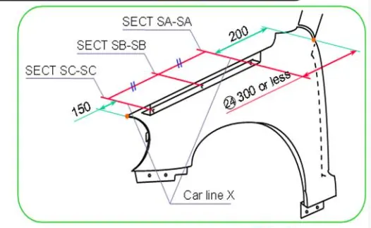
Drip Area: This region is an important region to be considered and there aredesign constraints to be followed.
a) The gap from the rear end of the fender and the front end of the fender. The rear end of the fender should have minimum 200mm gap for suffient mountings of cowl top (viper motor and its instruments).
Similarly we have a head lamp area. this head lamp will have a housing unit.In order to sufficiently place we have to have a minimum gap of 150mm.
b) Follow the master section for developing the drip area.
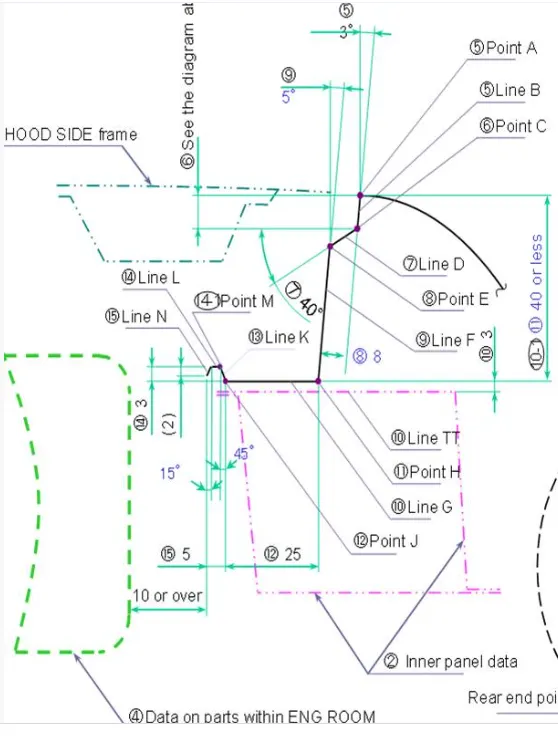
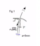
- The initiall 3 degrees is given for drawing reasons and production purpose.
- A minimum of 9mm length at angle of 40 degress from the 3 degress reference is needed in order to hide the engine compartments visible for a person viewing from the outside of the car. Basically we dont want the consumer to see any fastner area or any ugly area .
- The 40mm is basically given to achieve maximum productivity and if this length exceeds 60mm we get a spring back effect. Therefore it should ne within 40 mm to 60mm.
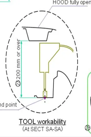
- Next the 25mm length is basially given in order to accomodate the tool to come and work perfectly inside
- The v structure design is basically given for to add strength.
 we have to make sure that after creating this structure we have to have atleast have 10mm gap front the fender drip area for easy assembling the components inside the engine compartment .
 -
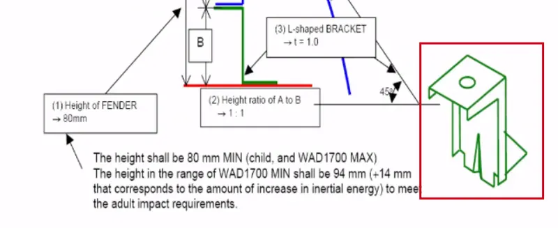
L Shaped Bracket
Procedure:
- Creating the surface for the mounting area:
- After Opening the File, Check the model and create the mount area regions.
- Use parallel curve option to offset the line to 5mm and split option split the class A surface to create a space for the mountings.
- Now, join the split surface excluding the top surface.
- Creating the Mounting flange part:
- To create the flange regions, use the sweep option near the space created for the mountings.
- After the sweep is created as per the master secion given, join the surfaces created.
- Creating the embosses and relief:
- After the mount flange are created, we need to create embosses and holes.
- To create embosses, create a sketch with the required shape. Project the sketch onto the mounting area but before that extract the surface.
- Now, split the surface to create a hole.
- Use the sweep command near the cut section. Now, offset the extracted surface.
- Trim the surfaces together and create a relief hole which is given to such that the screw is fitted into that hole.
- For the Drip Mount part, follow the details given and design the product.
- To create beaks, create the surface in a way that is angular and then trim the surfaces together.
- Giving the Fillets:
- Once the surface is trimmed, give the fillets near embosses and beads.
- Use the Extrude command followed by the edge fillet to create the sharp edges to the curved parts near the mountings.
- Creating the Solid:
- After the Surface is created, go to the part workbench and define the part body.
- Use the thick surface option to create the solid with a thickness of 1mm.
Embosses:
Sheet metal embossing is a stamping process for producing raised or sunken designs or relief in sheet metal. This process can be made by means of matched male and female roller dies, or by passing a sheet or a strip of metal between rolls of the desired pattern. It is often combined with foil stamping to create a shiny, 3D effect.
The metal sheet embossing operation is commonly accomplished with a combination of heat and pressure on the sheet metal, depending on what type of embossing is required. Theoretically, with any of these procedures, the metal thickness is changed in its composition.
The metal sheet is drawn through the male and female roller dies, producing a pattern or design on the metal sheet. Depending on the roller dies used, different patterns can be produced on the metal sheet. The pressure and a combination of heat actually "irons" while raising the level of the image higher than the substrate to make it smooth. The term "impressing" refers to an image lowered into the surface of a material, in distinction to an image raised out of the surface of a material.
In most of the pressure embossing operation machines, the upper roll blocks are stationary, while the bottom roll blocks are movable. The pressure with which the bottom roll is raised is referred to as the tonnage capacity.
Result:
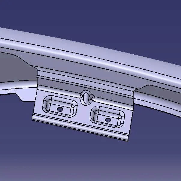
Drip Area Region:
Sill mount:
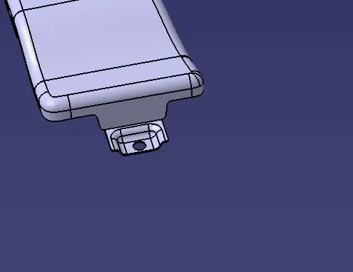
Bumper Area:
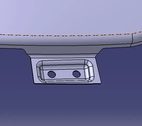
Cowl Area:
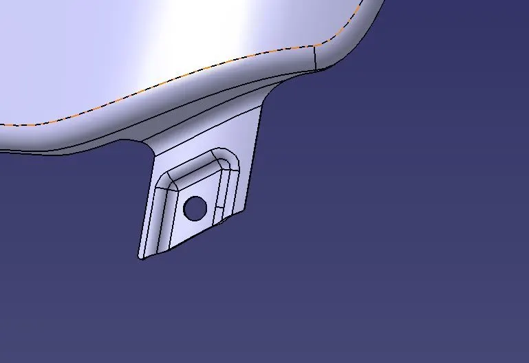
Wheel arch area:
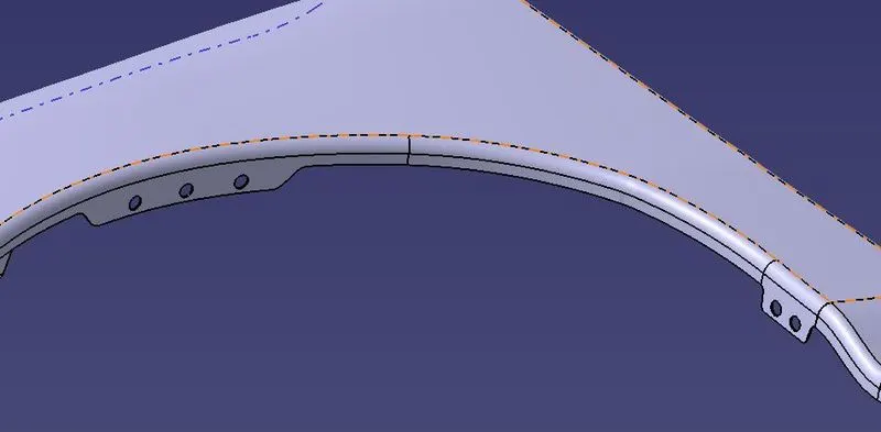
Final Model: