Fender Design Challenge
Introduction: Fender is the American English term for the part of an automobile, motorcycle or other vehicle body that frames a wheel well (the fender underside). Its primary purpose is to prevent sand, mud, rocks, liquids, and other road spray from being thrown into the air by the rotating tire. Fenders are typically rigid and can be damaged by contact with the road surface.
Objective: In this project we are going to design the mounts for the front fender such as drip, sill, bumper, A-pillar, cowl, and baffle. For this we are going to design the related mounts so that the all the mentioned parts are assembled easily.
Features/Tool Used:
- SKETCH
- OFFSET IN FACE
- CURVE ON SURFACE
- BRIDGE CURVE
- EMBOSS
- TRIM SHEET
- LAW EXTENSION
- FACE BLEND
- EDGE BLEND
- DART
- THICKEN
Description:
In this project as we said we are going to design the front fender mounts.
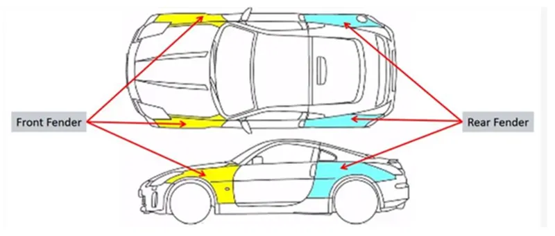
We have two types of fenders Full and Half bumper type.
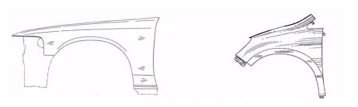
FULL BUMPER TYPE HALF BUMPER TYPE
Half bumper type fender manufacturing is more feasible than full one as it reduces manufacturing cost and less material wastage.
MASTER SECTION FOR DRIP AREA DESIGN:
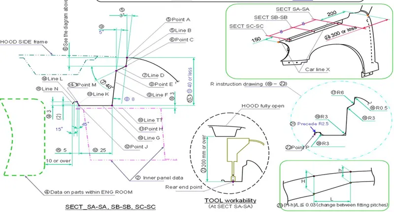
Here we develop drip mount as per Master section provided and design other mountings as per industrial design standards.
We are going to design drip area and other mountings on NX Cad.
First, we will be going to design the drip are which will going to mount on engine compartment.
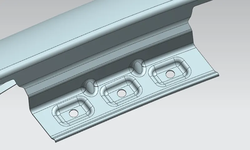
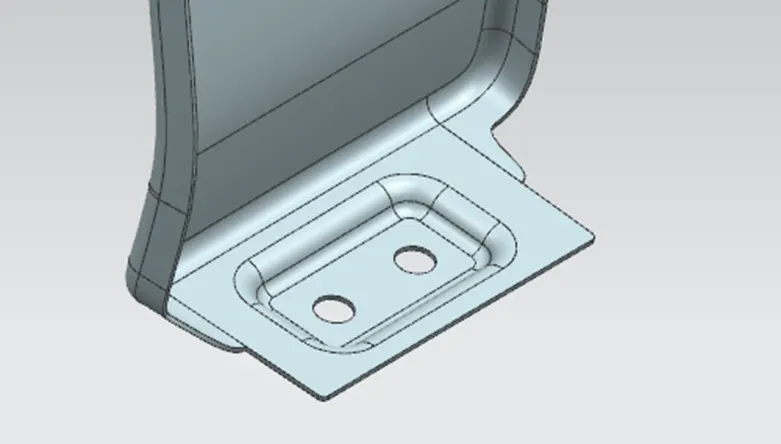
Drip Mount
As we can see in the above image of the fender we have provided embosses and holes for the fasteners and a minimum 5 mm flat area around the holes.
We have also provided darts in the corners to improve the strength of the drip area.
Sill Mount
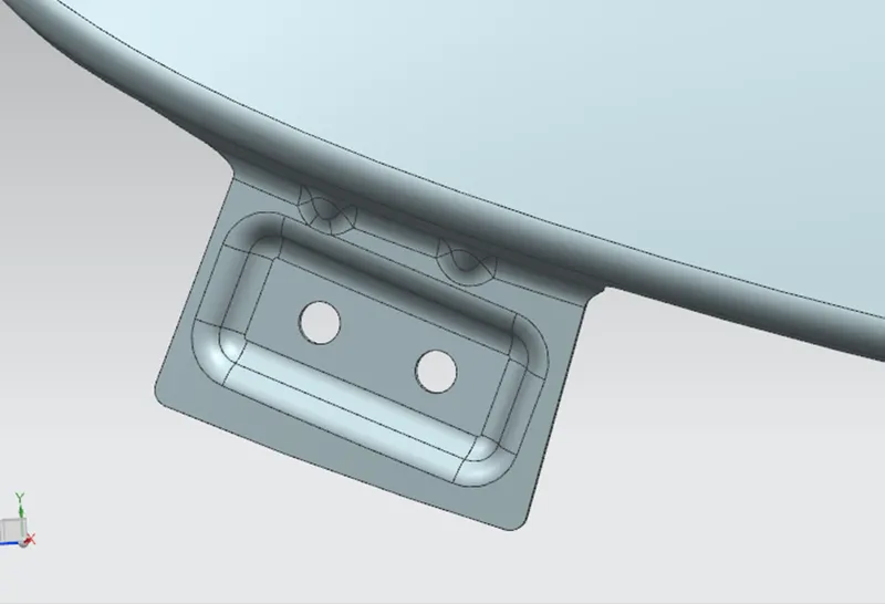
Like the drip mount area, we have also designed a sill mount area and make sure we provide relief in sharp corners to avoid stress concentration due to which chipping can happen and may cause part failure. We also must provide a radius on sharp edges.
Bumper Mount area
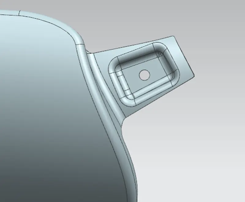
This mount is connected to the Bumper holes that have been provided for fasteners and darts are also provided to increase the strength of the mounting area. Make sure the sharp corners has to be remove to avoid the stress concentration.
A-Pillar Mount Area
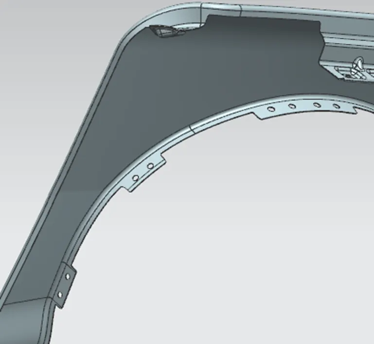
This mount area is connected to the A-Pillar of the car here we use a datum plane to create this mount as the surface is curved.
Baffle Mount Area
For mounting the baffle we have created a baffle flange on which the holes have been provided to mount the baffle here we have not provided any embosses.
Final Fender Design: -
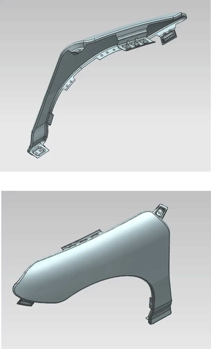
Conclusion: We have successfully designed the Fender as per the Standards and learned about the various mounting which is very important for the assembly of the fender with various other BIW parts of the vehicle.