Fender Design Challenge
Introduction
A fender is different than a bumper because it's a metal structure that frames the wheel well of your car, instead of the front or back. The fender extends between the front door to the front bumper covering the front wheels of the vehicle.
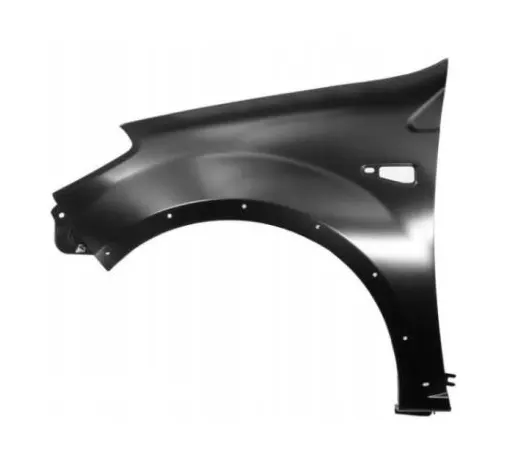
This fig shows the Front left side Fender for Car
Objective
Here the main objective is to design the Fender with all its attachment features like Side Mounting,Baffel Mounting,Bumper Mouting,Drip Area,Bottom Mounting from the given skin data.
Processes
- First of all we need to check the part for any available gaps on the skin data.As this part is a simple Class A surface so no need for checking the part.
- Now we need to create the required curve on the Surface by performing the Curve on Surface.
- We have to create the mounting places for that we need to Trim the Sheet as per our convenience to get our desired area for Side Mounting.
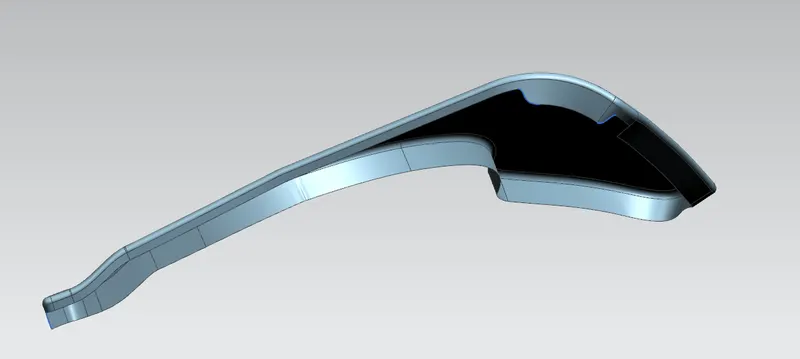
- We have the place for the side mounting area.
- As the side mounting area is fixed we can go for the Calculation of DRIP AREA.
- Drip Area-It is the place where the Fender is attached to the engine area.But to create this area we need to follow certain design rules for easy mounting of Fender with Engine & other parts as well(at back wipers housing & at front Head lamp housing).
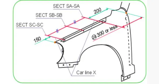
- Now we design the drip area as per the design guidlines.Mainly the guidline that concern is the Depth of the Drip Area
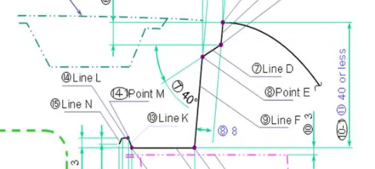
- So this depth is given for the ease access of the tightening tool or the repairing tool.And again if this depth is more than 60mm then the part itself create NVH which is called SPRING BACK EFFECT.To avoid this we need to provide DARTS in mid of the part for support.
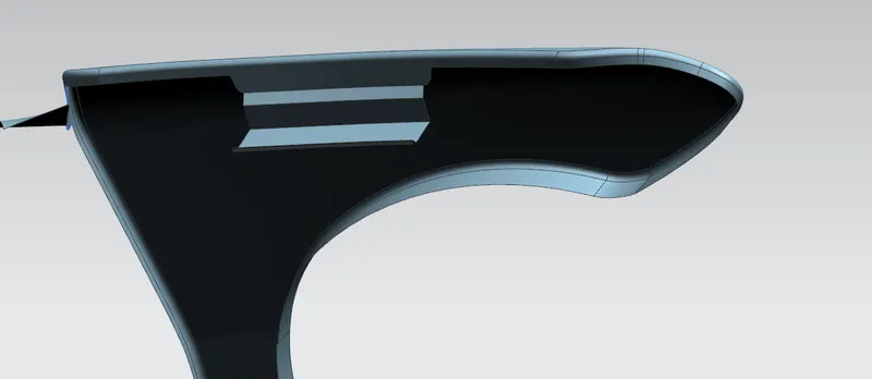
This is the required drip area at the desired place.
- Now we have to create the mountings for Bumper,Baffels etc.
- So to create that we need to perform the CURVE ON SURFACE & LAW EXTENSION to get our desired place for Mounting.
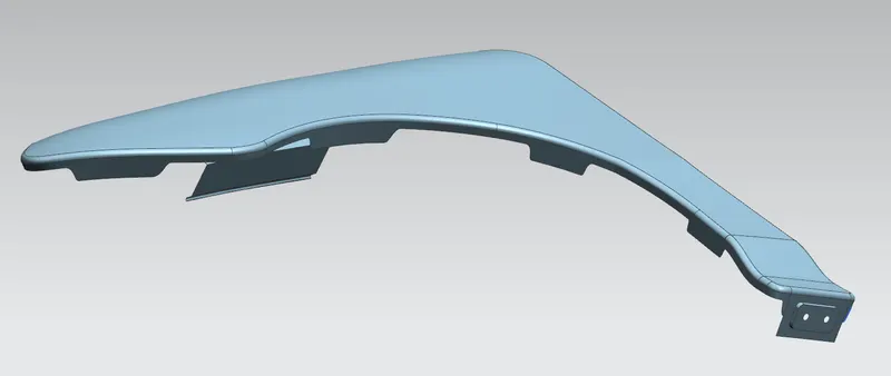
This above fig shows the mounting places for baffel,bumper & Side mounting
- To strengthen the part we need to create the Embosses at the place of mounting.
- Now the Part is ready and we need to Sew it with each other as the Law extended part treated separate entity.
- After Sewing all the generated parts we can go for Thickening for 0.75 mm.
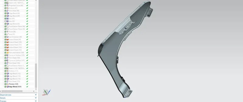
This fig shows all the attachment features with Edge fillets at required place.