Fender Design Challenge
FENDER Design
Objective: To design front fender from the given skin data and the master section provided with appropriate mountings.
Fender
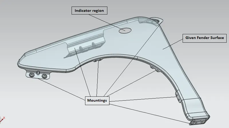
A fender is that curved portion of a car which acts as a barrier & which protects and frames its wheels thereby preventing sand, mud, rocks, liquids and other road debris from being thrown into the air by the rotating tire . In other words, the fender is a housing for the wheels that keeps road debris contained. If there was nothing covering the wheels, all kinds of debris would be kicked up by the rotating tires.
The fender not only protects your car from sustaining damage from road debris but it prevents this debris from being thrown up at other vehicles & pedestrians on the road.
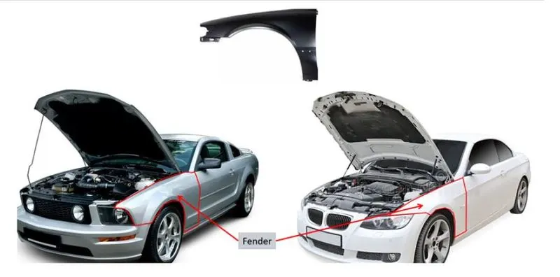
Most passenger automobiles have four fenders one over each wheel. For vehicles with narrow car body that exposes the tire, the fender is an exposed curve over the top of the tire. For wide body vehicles that cover the tire the fender forms the wheel well surrounding the tire and is not directly visible above the car body.
Fenders based on location:
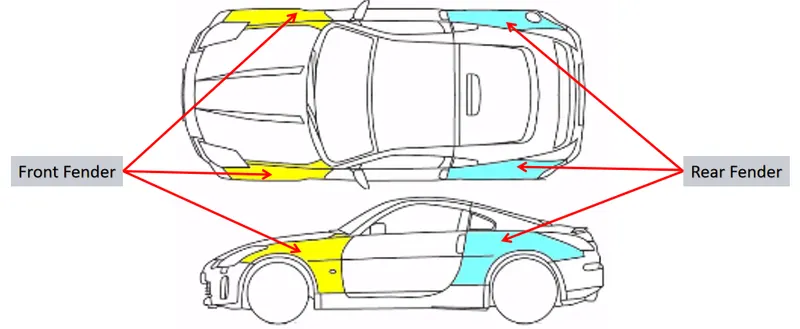
Front fender panels are located on the sides covering each front wheel from top. These panels cover the sides of the headlights to the hinge of front doors on the A-pillar. Vertically it runs from the hood to the wheel well.
Rear fender panels are located on the sides covering each rear wheel from top. They extend from the edge of the rear doors on the C pillar to the edge of the tail lights.
Types of fender
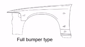
Full Bumper Type:
It is the traditional type of fender where more material consumption is observed. This type of Fender was used in old designs of automobiles where it increases the overall weight thus reducing the performance. Also maintenance is increased relatively due to more surface area.
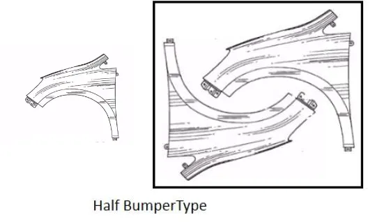
Half Bumper type:
It is modern type of fender consuming less material thus increasing overall performance. Its maintenance is relatively less compared to full bumper type due to reduction in the surface area.
The main productive aspect is that scrap is reduced drastically in half bumper type fender. In almost same blank size, TWO half Bumper type fenders can be produced as compared to only ONE Full bumper type fender thus reducing the overall cost of the product.
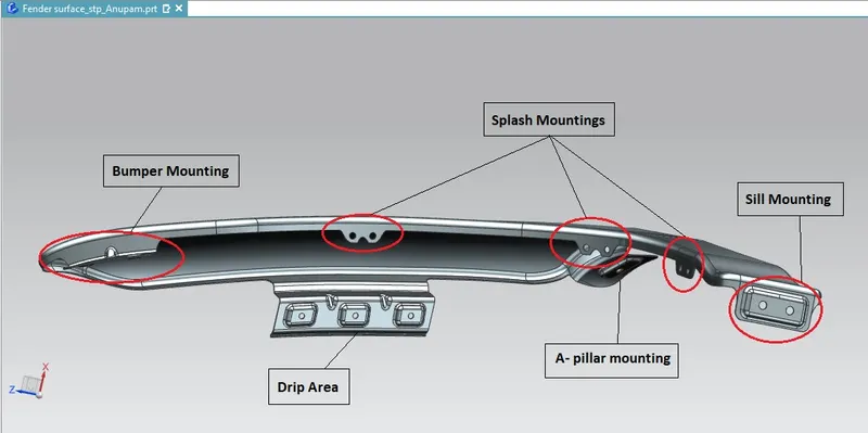
Mounting points on a Front Fender
The various mounting positions on fender are as follows
- Engine Mounting Area (Drip Area)
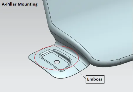
- A-Pillar Mounting Area
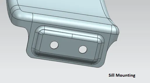
- Sill Mounting Area
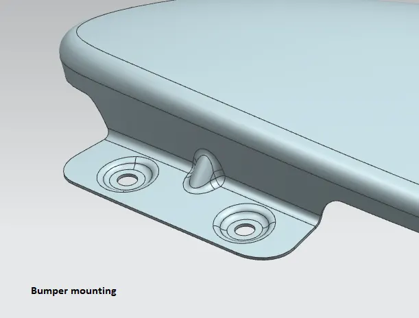
- Bumper Mounting Area
- Splash Mounting Area
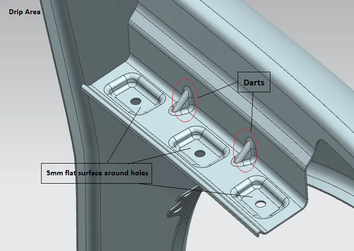
Engine Mounting Area (Drip Area)
It is the joining element of the fender to the Engine compartment. It is designed with some constraints as explained with the help of images below.
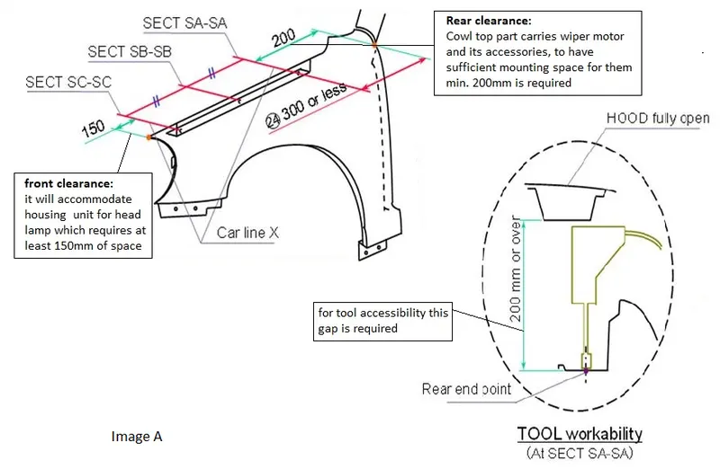
Image A shows the clearances given on Front fender on the front and rear side to meet design requirements.
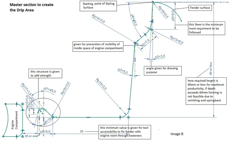
Image B above shows the master section of Drip area and design standards followed.
A-Pillar Mounting Area
It is located near the cowl of the vehicle where the fender is fastened with the bottom edge of the windshield.
Sill Mounting Area
It is positioned on lower most part of the fender used to join with sill of the vehicle.
Bumper Mounting Area
It helps in joining the fender. with the bumper of the vehicle.
Splash Mounting Area
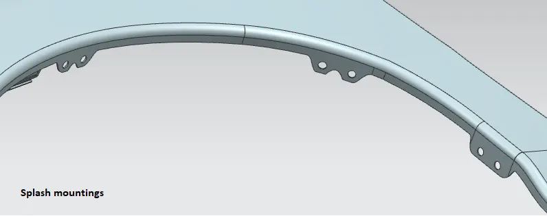
On this area Splash guards gets attached to the fender.
Wheel Arch
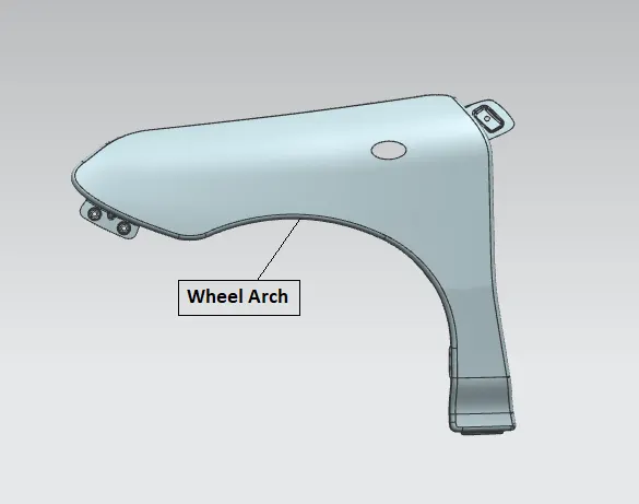
Wheel arch is the curvature given to the fender body since it houses the wheel.
The main objective to do wheel arch area calculations is to position the wheel under the fender with proper clearances. This is done to make sure that while the vehicle is in motion, the particles on the road like sand, dust, rocks etc gets chipped inside the fender surface for pedestrian safety.
There are various standards followed around the globe for the wheel arch requirements which are as follows:
1) Japan Standard
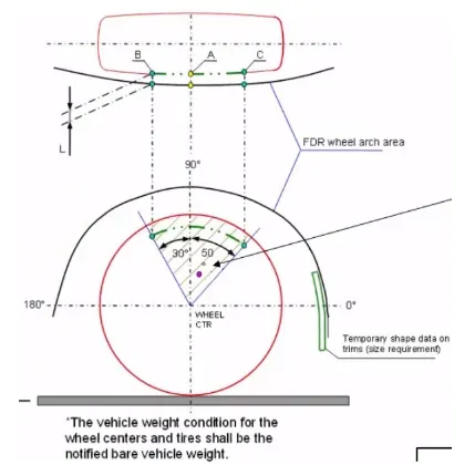
As per the Japan standard the clearance value L (i.e the gap between the tyre and the fender wheel arch) should not be less than 5mm at all the three points A, B & C as show in the above figure.
2) European Standard
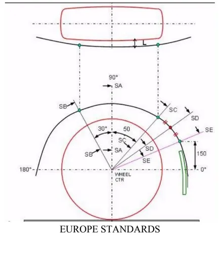
As per European standard, the clearance L should not be less than 10mm at all the 5 positions SA, SB, SC, SD, SE.
3) U.S Standard
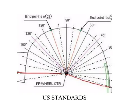
Lines are drawn from the centre for every 10 degrees from -20 to 180 degrees as shown in the figure above. As per the U.S standard the clearance gap between the wheel and the fender wheel arch should not be less than 5mm at every 10 degree angle.
Conclusion: Front fender was designed from the given skin data and master section provided with required mountings, considering all design constraints.