Fender Design Challenge
AIM: The main aim is to design the fender model with the necessary mounts using NX CAD.
The mounts which we need to design are as follows
- Drip
- Bumper
- A-Pillar
- Sill
- Cowl
FENDER
Fender is the American English term for the part of an automobile, motorcycle or other vehicle body that frames a wheel well (the fender underside). Its primary purpose is to prevent sand, mud, rocks, liquids, and other road spray from being thrown into the air by the rotating tire. Fenders are typically rigid and can be damaged by contact with the road surface.
Sticky materials, such as mud, may adhere to the smooth outer tire surface, while smooth loose objects, such as stones, can become temporarily embedded in the tread grooves as the tire rolls over the ground. These materials can be ejected from the surface of the tire at high velocity as the tire imparts kinetic energy to the attached objects. For a vehicle moving forward, the top of the tire is rotating upward and forward, and can throw objects into the air at other vehicles or pedestrians in front of the vehicle.
Procedure:
- Creating the sections:
- After Opening the File, Check the model and create the mount area layouts.
- Use parallel curve option to offset the line to 5mm and split option cut the class A to create a space for the mountings.
- Now, join the split surface excluding the top surface.
- Creating the Mount part:
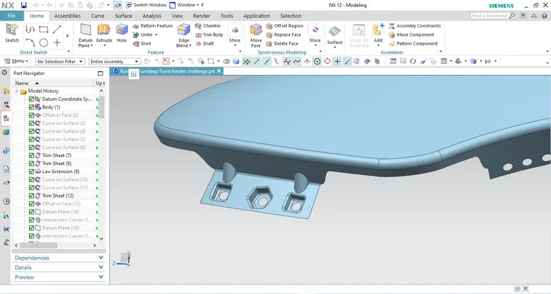
- To create the mount regions, use the sweep option near the space created for the mountings.
- After the sweep is done as per the design model given, join the surface created.
- Creating the embosses and relief:
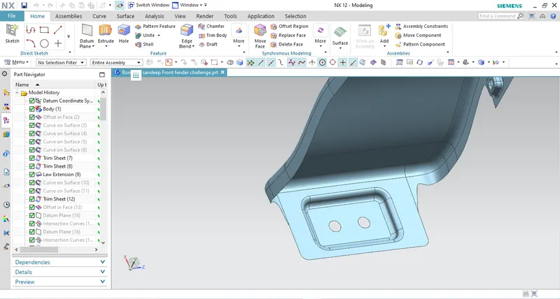
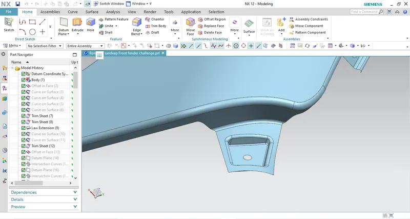
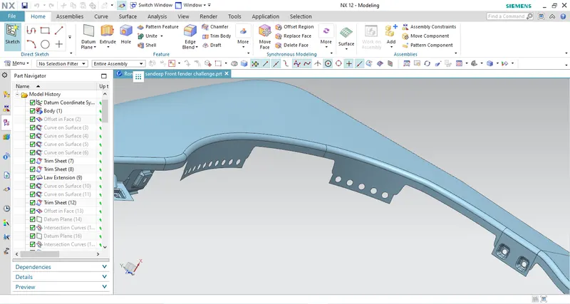
- After the mounts are created, we need to create embosses and holes are to be given.
- To create emboss, create a sketch with the required shape. Project the sketch onto the mounting area but before that extract the surface.
- Now, split the surface to create a hole near the projected area to create an emboss.
- Use the sweep command near the cut section. Now, offset the extracted surface.
- Trim the surfaces together and create a relief hole which is given to such that the screw is fitted into that hole.
- For the Drip Mount part, follow the details given and design the product.
- To create beaks, create the surface in a way that is angular and then trim the surfaces together.
- Giving the Fillets:
- Once the surface is trimmed, give the fillets near embosses and beads.
- Use the Extrude command followed by the edge fillet to create the sharp edges to the curved parts near the mountings.
- Creating the Solid:
- After the Surface is created, go to the part workbench and define the part body.
- Use the thick surface option to create the solid with a thickness of 1mm.
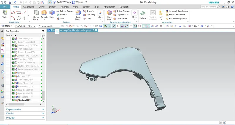
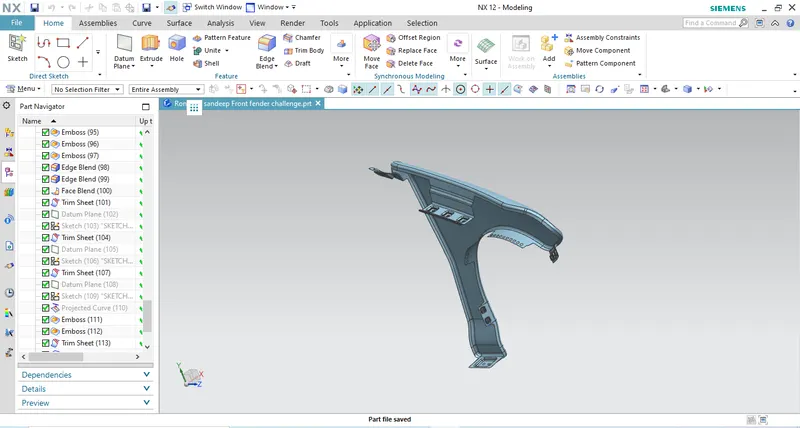
OUTPUT:
DRIP MOUNT:
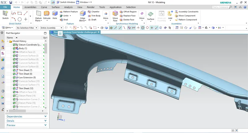
SILL MOUNT:
A-PILLAR MOUNT:
COWL MOUNT:
BUMPER MOUNT: