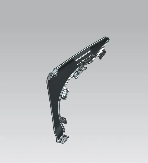
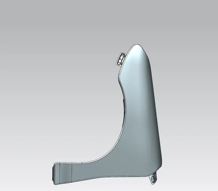
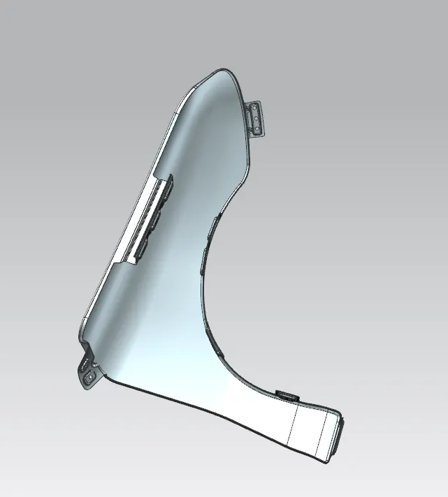
Fender Design Challenge
Fender Design
Introduction : Fender is the US English term for the part of an automobile (vehicle body) that frames a wheel well. Its primary purpose is to prevent sand, mud, rocks, liquids and other road spray from being thrown into the air by the rotating tyre.Body side has integrated fender whereas front fender is a separate closure component. Front fender is one of the side closing components.The fender also plays a major role to prevent injuries for the pedestrians. This anti chipping is also a pedestrian safety criteria because these stones which get chipped from the tyre may tend to hit the pedestrian also so, a strong fender is recommended for the safety of the pedestrians.
Types of Fender : There are two types of fenders , they are :
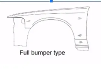
- Full Bumper type.
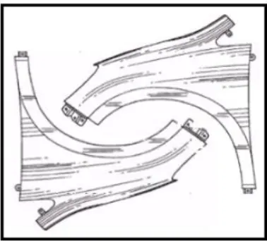
- two Half Bumper type fenders can be made from same blank of sheet
Reason for the use of half bumper type fender :
- For creating the full bumper type, the blank of sheet used for its creation is really big and there is a wastage of sheet metal.
- Whereas in half bumper type there is a high possibility to reduce the wastage.
- By slightly increasing the blank size two half bumper type fenders can easily be produced. This will reduce the blank cost and a better fender can be made available to customers at a cheap rate.
- The half bumper type will allow the use of a lot of plastic on the bumper which will reduce some particular proportion of steel weight thus increasing the performance of the vehicle.
Mounting points of the front fender :
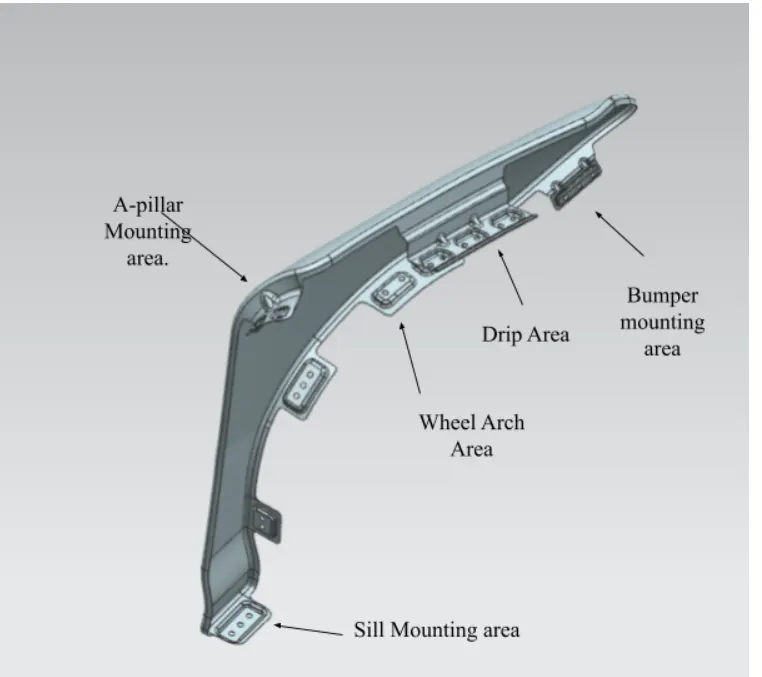
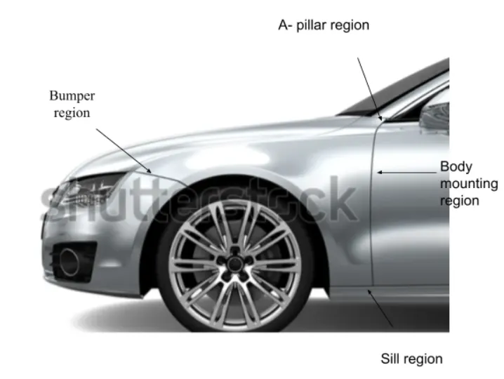
There are 6 mounting points in a fender :
- Body.
- A pillar.
- Sill.
- Cowl.
- Drip.
- Bumper.
Design Consideration :
Master section
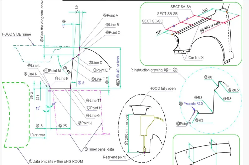
- The cowl part will be carrying the viper motor and its instruments so the 200mm will be taken from the cowl part and then the drip area will be made.
- In the front there is going to be a headlamp, this headlamp will have a housing unit and to have sufficient space for the housing unit, at least 150mm distance is taken from front and then the drip area is made.
- The length of the drip area is defined by the length of the fender.
- A flange of 7 to 8mm is created as shown in the master section in order to prevent the visibility of the viewer from outside and doesn't make the drip area visible from outside.
- There should be no part near the engine room for at least 10 mm or more.
- Side reference point of the hood to the end of the fender should not exceed 47.5mm.
Manufacture:
- For production purposes 3 degree opening is given for drawing reasons.
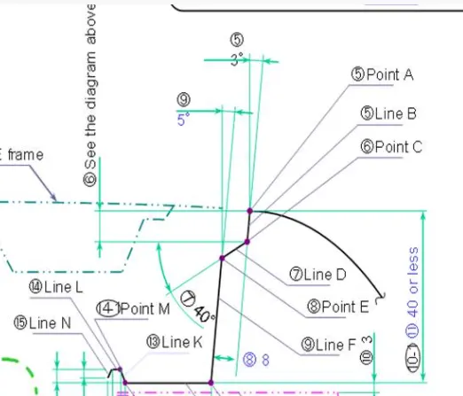
- The width of the drip area is taken around 35 to 40 mm to allow the tool to work properly.
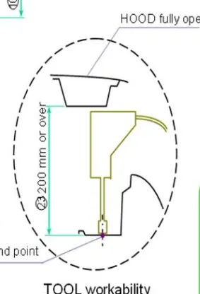
- There must be a 200mm gap between the hood in open condition for the accessibility of the tool.
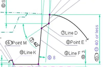
- Hood side drip depth must be 40mm or less as maximum productivity is achieved at the depth of 40mm, if the depth exceeds 40mm, rigidity bead is to be provided and forming is not feasible if the depth exceeds 60mm due to spring back effect.
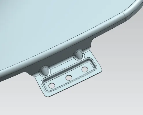
- Emboss and darts are added to give strength.
Images :