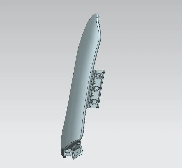
Fender Design Challenge
FENDER DESIGN
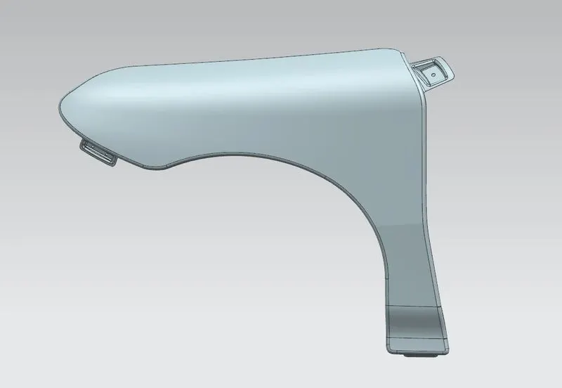
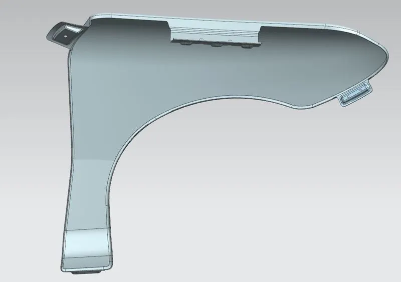
Fender is the pressed and formed sheet metal part mounted over the road wheels of an automobile that frames a wheel well and the primary purpose is to reduce the splashing of mud, water and other road spray into the air by the rotating tire
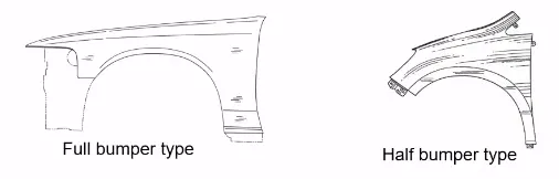
There are two types of fenders.
- Full bumper type fender: Full bumper type fender is a traditional type of fender where more material consumption is observed. This type of fender is used in old design of automobiles where it increases the overall weight and thus reduces the performance of car.
- Half bumper type fender: Half bumper type fender is a modern design where less material consumption is observed, so productivity increases by reducing size of blank and thus providing more performance.
Design considerations for sheet metal to make manufacturing success
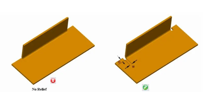
- Bend Relief Parameters: When a bend is made close to an edge, the sheet metal may tear unless bend relief is given. Bend relief helps in controlling the sheet metal material behaviour and prevents unwanted deformation when a bend does not extend the entire length of a part.It is recommended to use rectangular relief. The minimum depth (D) of a bend relief should be equal to the material thickness plus the radius of a bend. The minimum width (W) of a bend relief should be equal to 1.5times the material thickness
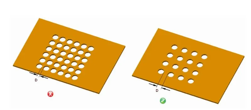
- Spacing between holes: It is recommended that minimum distance between the holes in a sheet metal should be equal to 1.2 times the material thickness.
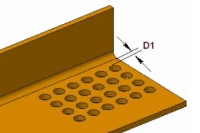
- Hole to bend distance: When a bend is made too close to the hole, the hole may become deformed. So, it is recommended that the minimum distance from the edge of a circular hole to a bend should be 3 times the material thickness.
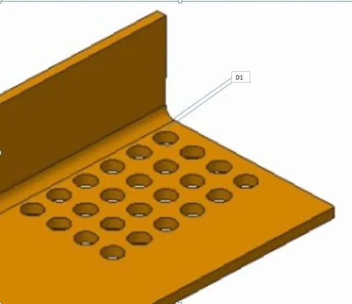
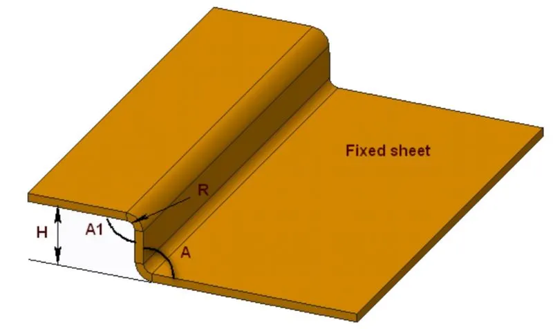
- Offset Bend Parameters: An offset bend, also called as joggle is made up of two very short bends formed simultaneously. It is used to joggle other sheet metal surface or overlap of a sheet. So, it is recommended that the bend angles (A1) should be obtuse angles or right angles and the maximum height (H) of an offset bend should be five times of the material thickness.
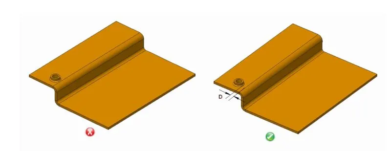
- Distance between offset bends and extruded hole: The minimum recommended distance from the bend’s inside surface to the major diameter of extrusion should be equal to 2.5 times the material thickness.
Tools and features used in designing of fender.
- Law of extension: Law of Extension creates flanges or extensions when a particular direction is important or when it is necessary to reference the existing face.
- Embossing: Emboss command use to create an embossing by modify a body with faces made by projecting a section along a vector, with options for end cap location and shape.
- Trim Sheet: Trim sheetcommand use to trim off a portion of a sheet body using curves, faces, or datum planes.
- Bridge curve: The bridge curvesare perpendicular to the surface edge at the intersection point
- Face Blend: Face Blendis primarily used to blend between faces of separate bodies. It can also be used to blend between faces of a single body.
Various processes involved in fender manufacturing are:
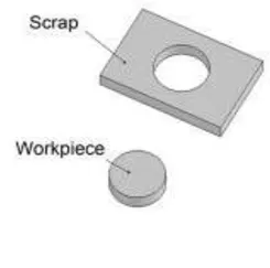
- Blanking: It is a metal fabrication process, in which a metal work piece is removed from the primary metal strip or sheet when it is punched. The material that is removed is used as new metal work piece or blank.
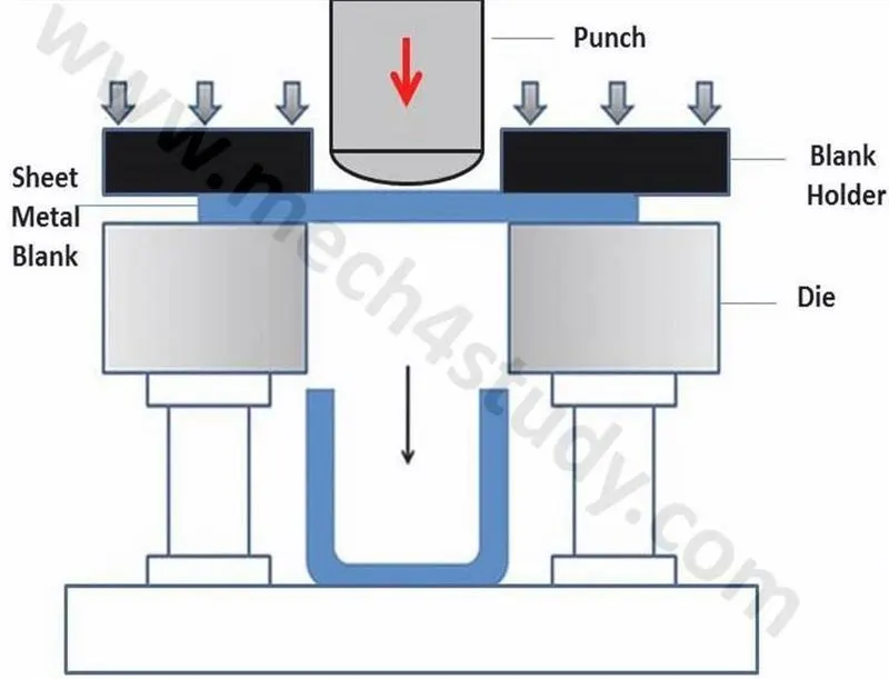
- Drawing: Deep drawingis a sheet metal forming process in which a sheet metal blank is radially drawn into a forming die by the mechanical action of a punch. It is thus a shape transformation process with material retention. The process is considered "deep" drawing when the depth of the drawn part exceeds its diameter.
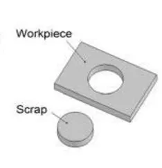
- Piercing: It is a shearing process, here raw material pierced with a machining tool, resulting in the creation of hole.
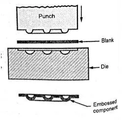
- Embossing: It is a stamping process for producing raised or sunken designs or relief in sheet metal.
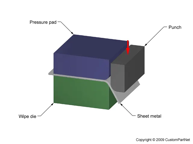
- Bending: Bendingis a manufacturing process that produces a V-shape, U-shape, or channel shape along a straight axis in sheet metal.
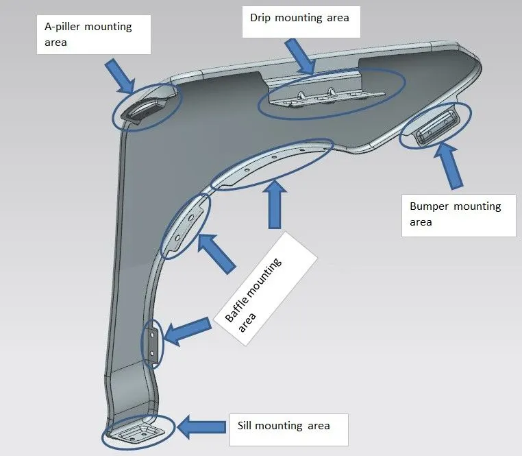
Different mountings on the fender
- A-Pillar mounting
- Drip area
- Sill mounting
- Bumper mounting
- Baffle mounting
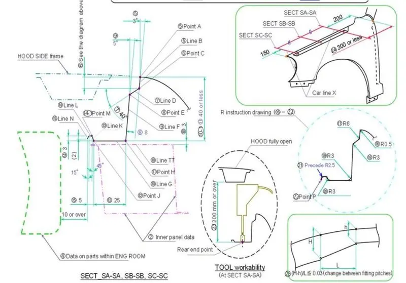
Master Section of drip area: It is a 2D representation of profile showing the required dimensions to design the mountings on fender to different required regions of car body.
Design considerations
- Embosses are provided to increase the strength and minimum draft angle is provided to satisfy drawing process.
- Ribs are provided at required areas to add extra support and to avoid spring back.
- Minimum 5mm flat surface is maintained around mounting holes.
- Every sharp corners are provided with radius (filleted) to avoid the stress accumulation.
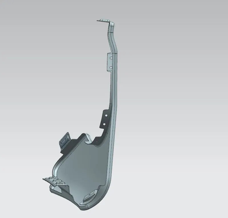
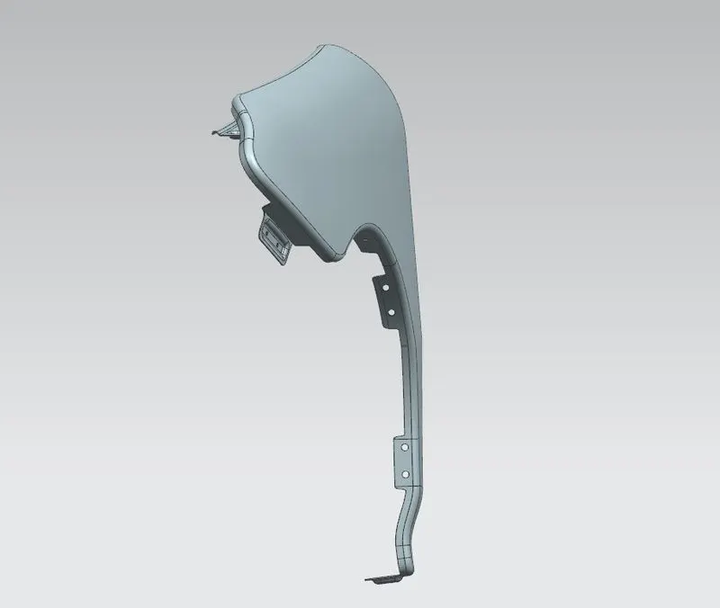
Final Design of Front Fender