Fender Design Challenge
Aim: To design Front fender using the given Class-A surface and master section.
Description:
Software used: Siemens NX 12
Fender:
A Fender is merely a housing for the wheels that prevents road debris from being thrown up by the rotating tires. However, fenders are also able to absorb impact from minor collisions. In this way, the fender can act as an extension of the bumper in terms of its ability to absorb the energy from a collision. Fender is also called ‘Mudguard’ in Britain, India and few other countries, as it guards the riders and pedestrians from mud sprayed by the tyre.
 |
| Front Fender |
Significance of Fender:
The purpose of a fender is to keep mud, rocks, and other road debris from being thrown around by the tires. In other words, the fender is a housing for the wheels that keeps road debris contained. If there was nothing covering the wheels, all kinds of debris would be kicked up by the rotating tires.
The fender not only protects your car from sustaining damage from road debris but it prevents this debris from being thrown up at other vehicles on the road. This is why vehicles with large, oversized tires are often required by law to install fender flares.
Manufacturing Process:
Fenders are manufactured mostly by stamping method. The technical definition of metal stamping is that it’s a type of cold forming process that uses extreme force and/or speed to permanently alter the shape of a piece of metal. For sheet metal stamping, the work piece is sheet metal.
The manufacturing process includes the following steps firstly, unfolding and shearing are carried out on a plate, wherein a proper cold roll specification is selected at first, a cold roll is unfolded, and then the unfolded cold roll is placed between core and cavity and by applying appropriate load stamping is done. If the design of the fender is complex then the stamping is carried in multiple steps to obtain the required design.
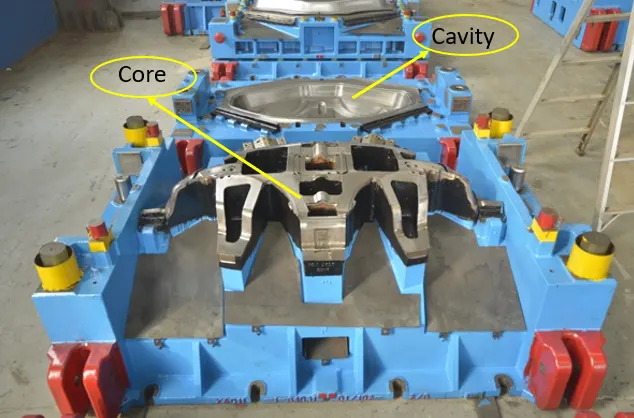 |
| Core and Cavity for Front fender. |
Types of fenders:
1. Full Bumper type Fender:
 |
 |
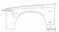
| Full Bumper type Fender | |
These types of fenders were too long and blank size used to obtain these fenders was more, which increased the manufacturing process and cost. Most of the vintage cars can be seen with these type of fenders.
2. Half Bumper type Fender:
 |
|
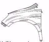
| Half Bumper type Fender | |
All modern cars use these types of fenders because they utilize less material and have more strength as compared to the other type.
Mounting of Front Fender:
Entire front fender is mounted along these portions of the Car.
- Drip area
- A Pillar
- Sill
- Baffle
- Bumper
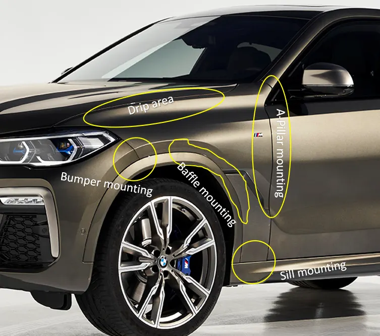 |
| Mounting of Front Fender in cars. |
Drip area mounting:
Mounting for drip are is created as per the given master section (shown in below figure).
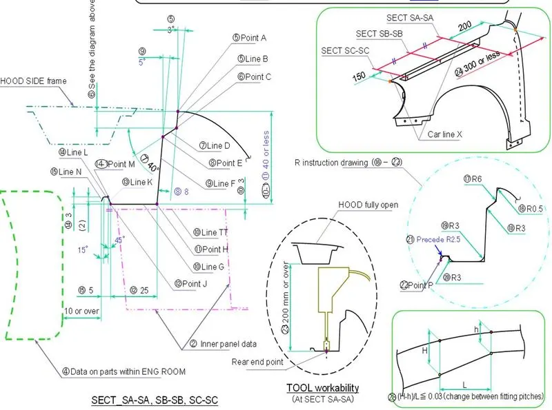 |
| Master section for Drip area mounting. |
This mounting helps fender to mount on the engine compartment.
Procedure:
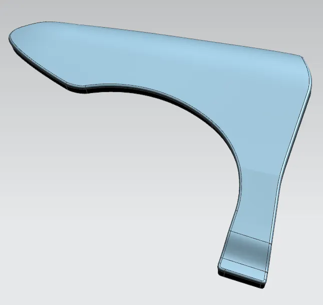
1. The length of flange given along the Class-A surface is more and need to be reduced. This is done by offsetting the edge curve using ‘offset curve in face’ option and then create smooth flowing curves on these flanges such that there should be individual flanges for mounting with the Drip, Cowl and Sill portions.
 |
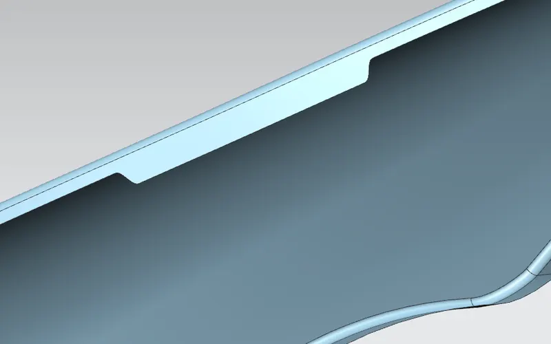 |
| Given Class-A surface | Flange for Drip area |
2. A flange of 8mm at 400 is created using ‘Law extension’ tool again using same tool the drip mounting portion is created according to the given master section.
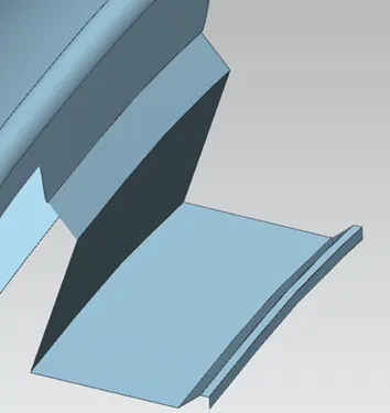 |
| Drip area flange according to master section. |
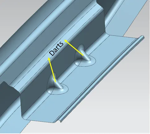
3. Darts are provided on the flange portion to provide local strength to the flange. Blends are applied on the sharp edges to reduce the stress concentration.
 |
| Darts to provide local strength. |
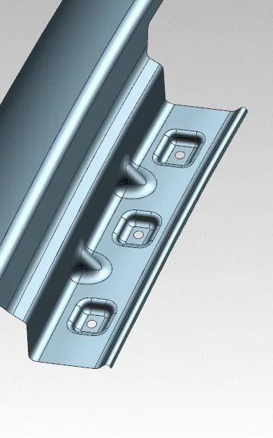
4. By entering into the sketch workbench draw the profile for the emboss and the depth of the emboss should be around 3 to 5mm, I’ve used 4mm of emboss depth. Provide holes on the emboss for bolting operations and every sharp edge is made smooth using bridge curve tool.
 |
| Flange with mounting holes. |
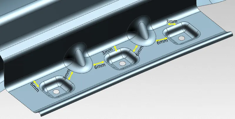
Gap of minimum 3mm should be provided between two blends so that the tool can be operated easily.
 |
A-Pillar mounting:
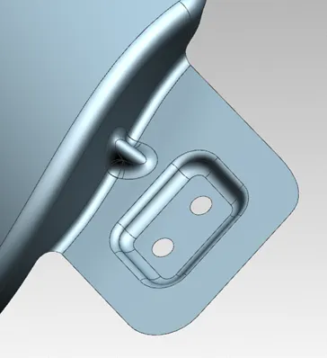
A-pillar is the part of the body along the side boundaries of the windshield. It is subject to strong legal requirements regarding the driver’s visibility. This portion is mounted on the A-pillar and sometimes it is mounted on the body. The design for this mounting varies from model to model. In some cars the A-pillar mounting on fender is designed in such a way that the mirror, fender and the A-pillar are mounted together.
The design procedure is quite simple, a flat surface is created perpendicular to the flange and further embossing and holes are created for mounting. At some portion embossing is not done as push clips are used for mounting at these portions.
 |
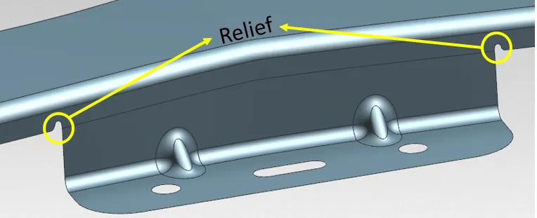 |
| A-pillar mounting | |
Baffle mounting:
This helps to mount the fender lining on fender. Holes are created on the flanges where the fender lining is mounted using the push clips.
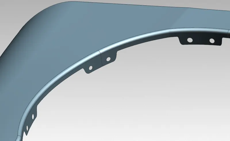 |
| Baffle mounting |
Bumper mounting:
A Bumper is located on the front and rear of a vehicle. The purpose of a bumper is to absorb the impact of minor collisions.
In the early days of the automobile, bumpers were a more distinct component that was noticeably separate from the rest of the car’s body. But as automotive technology advanced, bumpers became more integrated with the rest of the car’s body. The purpose of the modern bumper remains the same, but the bumpers on many vehicles (namely sedans and crossovers) are less visually noticeable than they once were. This portion is mounted along bumper using the push clips.
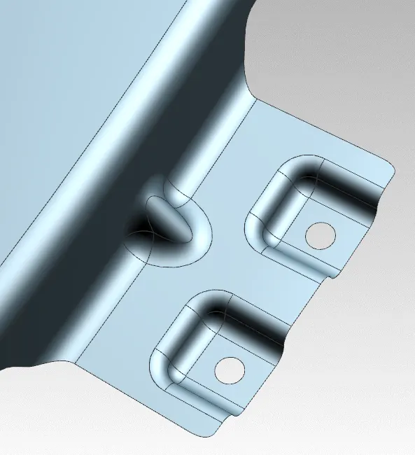 |
| Bumper mounting |
Sill mounting:
It is the bottom portion of the car and the fender is mounted at this portion using blots and nuts. Embossing is done in order to provide local strength to the flange.
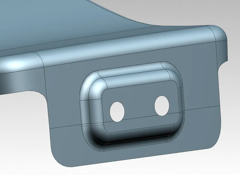 |
| Sill mounting |
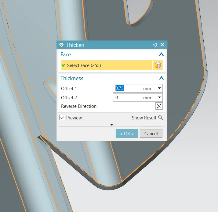
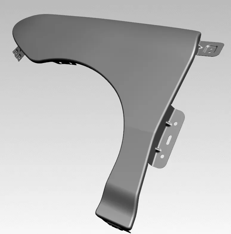
Finally, thickness is a of 0.75mm is applied in the downward direction of the Class-A surface.
 |
 |
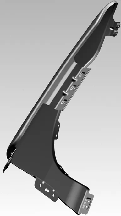 |
| Rendered Front Fender. | |
Conclusion:
Drip area on the fender is designed according to the given master section.
Fender is designed by following the standards (so that it should be manufacturable) and darts are applied to provide local strength.