Fender Design Challenge
DESIGN OF CAR FRONT FENDER USING SIEMENS NX-CAD
OBJECTIVE
To design car front fender with A-Pillar, Bumper, Cowl, Drip area and Sill Mountings with the help of Master section and data provided using the SIEMENS NX-CAD
INTRODUCTION
FENDER
Fender is the American English term for the part of an automobile, motorcycle or other vehicle body that frames a wheel well (the fender underside). Its primary purpose is to prevent sand, mud, rocks, liquids, and other road spray from being thrown into the air by the rotating tire. Fenders are typically rigid and can be damaged by contact with the road surface.
Sticky materials, such as mud, may adhere to the smooth outer tire surface, while smooth loose objects, such as stones, can become temporarily embedded in the tread grooves as the tire rolls over the ground. These materials can be ejected from the surface of the tire at high velocity as the tire imparts kinetic energy to the attached objects. For a vehicle moving forward, the top of the tire is rotating upward and forward and can throw objects into the air at other vehicles or pedestrians in front of the vehicle.
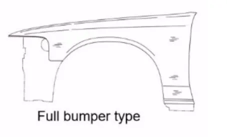
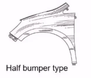
Fender mainly consists of two types,
FULL BUMPER TYPE
- It covers more area and consumes more material compared to half bumper
- Scrap material is more compared to half bumper
HALF BUMPER TYPE
- It covers less area and consumes less material
- In this a single sheet can be used to produce more than one bumper
DESIGN METHODOLOGY
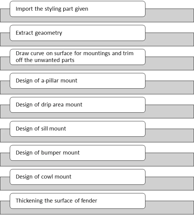
The design methodology of the fender is explained with the help of flow chart for easy and better understanding
FLOWCHART
DESCRIPTION
There are various tools used to design the fender in SIEMENS NXCAD they are described as follows,
Features Used
Extract Geometry: Creates associative copies of bodies, faces, curves. Points, and datums and associative mirrored copies of bodies, within the same part.
Extend Sheet: Extends a sheet body by distance or to the intersection with another body.
Offset Curve in Face: Offsets curves along the faces on which they lie.
Law Extension: Creates a law -controlled extension from a base sheet, dynamically or based on laws for distances and angle.
Trim Sheet: Trims off a portion of a sheet body.
Face Blend: Adds Tangent bend faces between selected sets of faces. The blend shape can be circular, conic, or law controlled.
Edge Blend: Rounds sharp edges between faces. The radius can be constant variable.
Curve on face: Creates a surface spline feature directly on a face.
Thicken: Creates a solid body by adding thickness to a set of faces.
Trim Body: Trims off a portion of a body.
Trim and Extend: Trims or extends a set of edges or faces to the intersection with another set of edges or faces.
Project Curve: Projects curves, edges, or points onto faces or planes.
Emboss: Modifies a body with faces made by projecting a section along a vector, with options for end cap location and shape.
Datum Plane: Creates a datum plane used to construct other features.
Datum CSYS: Creates a datum coordinate system used to construct other features.
Sew: Combines sheet bodies by sewing common edges together, or combines solid bodies by sewing common faces.
STYLING PART
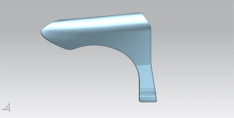
It is the part given to design the fender with the A-Pillar, sill, cowl, bumper and drip area mountings by the styling team.
MASTER SECTION
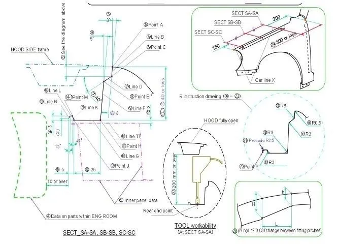
- These gives complete information about designing drip area.
- Then A-pillar, Sill, Cowl and Bumper mountings are designed on basis of Engineering standards.
DESIGN OF A-PILLAR MOUNTING
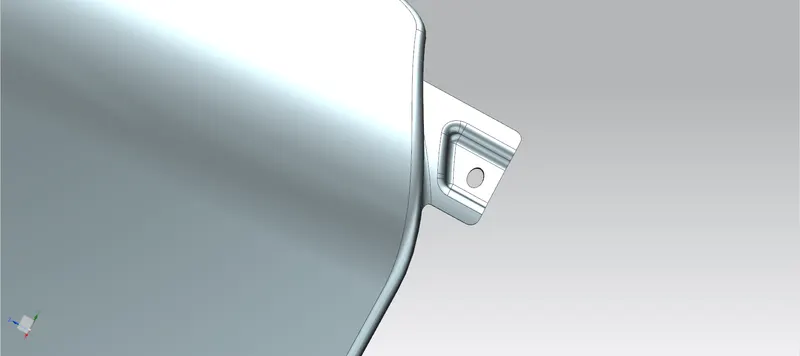
Initially the skin data provided by styling team is to be extracted. Then the outer edge of fender was offset inwards to a required length. By using Trim sheet unwanted portions were trimmed out easily at required places. By using the law extension, the A-Pillar were extended and trimmed on sides to get a flat edge. Then flat Emboss is created by creating plane and using it as reference for Emboss creation. Sketches are drawn on Datum plane and project to the surface. Then for creating a fastener hole which needs around 5mm gap to stiffen it, trim command was used. Required blends are added to all edges using face blend
DESIGN OF BUMPER MOUNTING
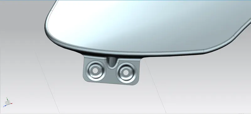
Firstly, unwanted portions were trimmed off using curve on surface and trim surface command. Then datum plane is created for getting Flat Emboss. Sketches are drawn on plane and projected to surface for creating required Emboss. Embosses for a draft are given in a way that satisfies requirements of manufacturability. Finally required blends were applied.
DESIGN OF COWL MOUNTING
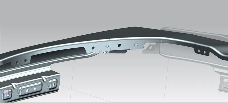
The main requirement of Cowl mounting is to fit the splash mounting on it which protects the Engine compartment from debris that enters during driving. For placing splash their mounting areas were created with required holes for placing fasteners. Then datum plane is created for drawing sketches and projecting it on to the required surface. Using trim sheet holes are created on basis of sketches.
DESIGN OF DRIP AREA MOUNTING
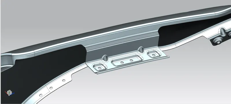
On basis of Master section as reference drip mounting were created. The drip area must be 150mm apart from the front edge so that drip mounting won’t disturb the head lamp mounting. In same way from backwards the drip area must be 200mm apart from back edge to avoid the coincidence with engine cables. For creating this drip area at required distance two planes were created and then intersection curve was used to create the curve on surface as required. Then remaining unwanted portions are trimmed out. The drip area was created in required angle as provided in master section. After creating the law extension as required by the master section the required emboss were created. Then datum plane is created for creating the flat emboss as per dimensions. Then holes are created by using trim sheet for creating the fasteners. Required blends are created for improving the aesthetics of fender.
DESIGN OF SILL MOUNTING
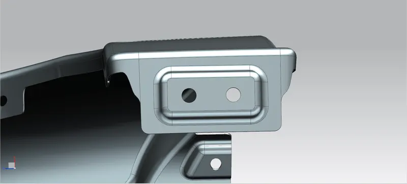
For creating the Sill Mounting the extra portions were trimmed off. Then datum plane was created and required sketch was drawn and projected. Some holes for placing fasteners are created and edges were blended together. Embosses are created on basis of plane for creating flat.
ISOMETRIC VIEW:
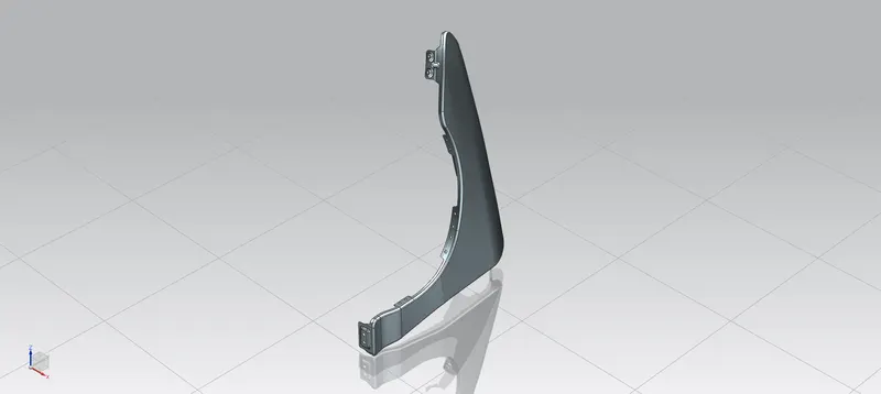
TOP VIEW:
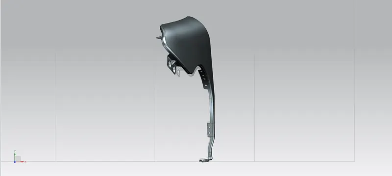
FRONT VIEW:
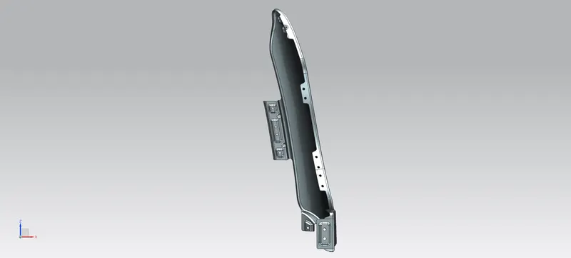
RIGHT SIDE VIEW:
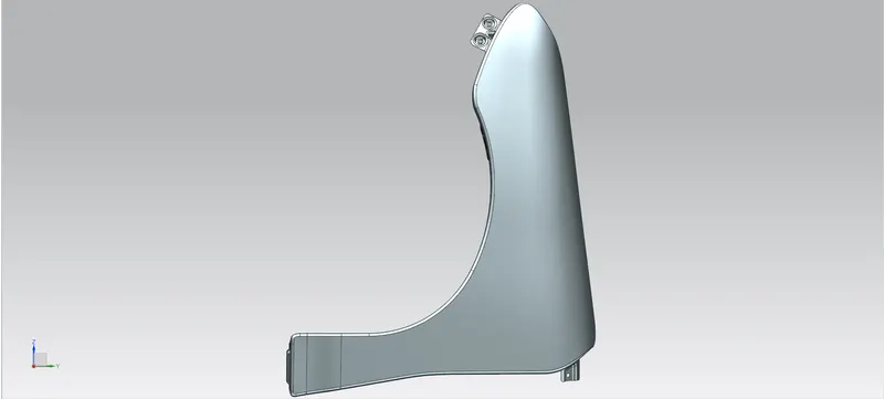
BOTTOM VIEW:
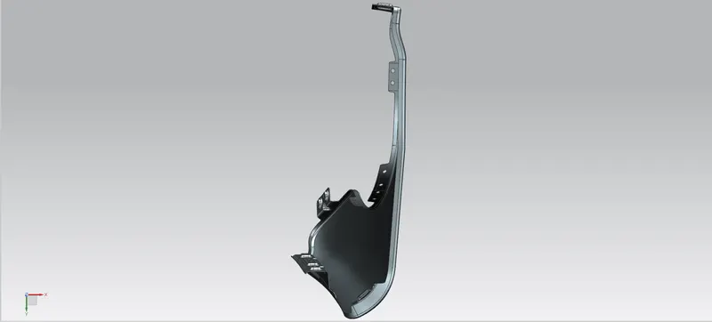
BACK VIEW:
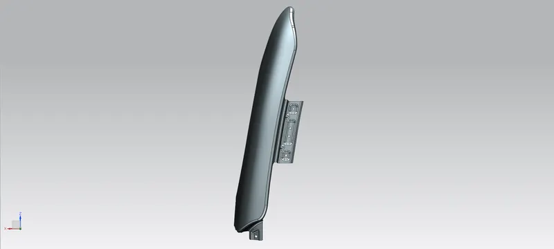
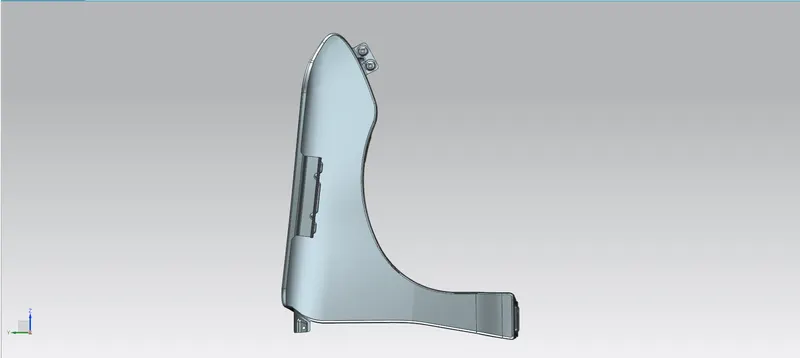
LEFT SIDE VIEW:
CONCLUSION
The front fender of a car is designed with A-Pillar, Bumper, Cowl, Drip and Sill mountings with the help of master section and data provided using the SIEMENS NXCAD.
LINK:https://drive.google.com/file/d/1huXoXMSOcqNAKJFMzynajS2yYBcFgV_c/view?usp=sharing