Fender Design Challenge
Aim:
Designing the fender using Catia V5
Objective:
Design the fender including the following mounting area :
- Drip
- A-pillar
- Sill
- Bumper
- Baffle and splash
Introduction:
Fender is the American English term for the part of an automobile. Its primary purpose is to prevent sand, mud, rocks, liquids,and other road wastes from being thrown into the air by the rotating tire.
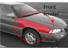
TYPES OF FENDERS:
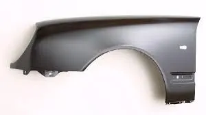
There are 2 types of fenders depends upon their production approach.
1. Full Bumper Type.
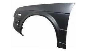
2. Half Bumper Type.
Procedure :
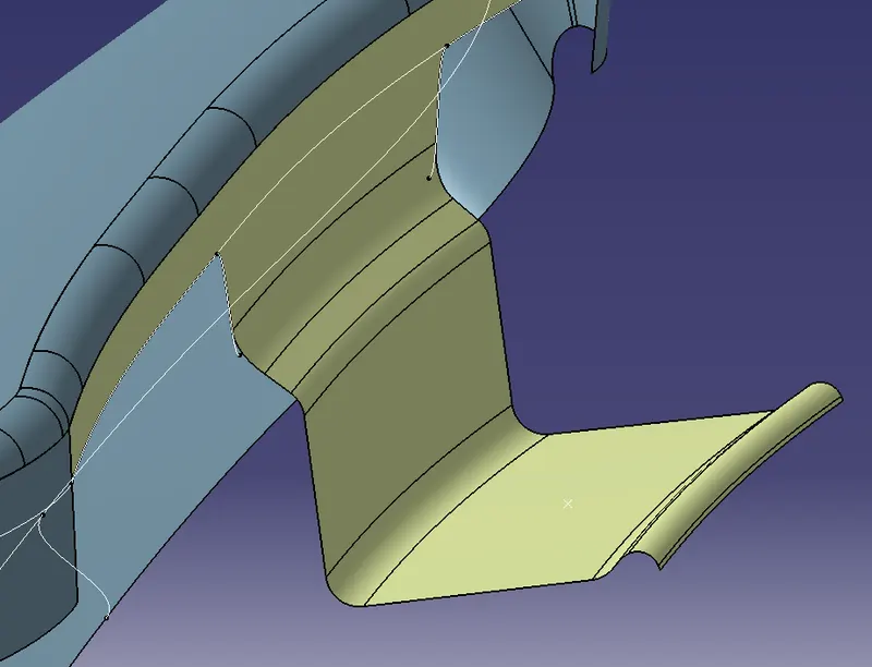
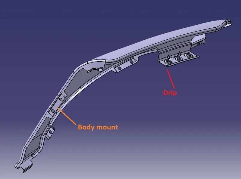
Drip mounting :
This region is mounted below the hood inner panel which needs to be flush when the hood is in a closed condition and also there should be very fewer gaps.
The drip area is either spot welded or in some cases bolted down via self-tapping screws.
The following design sheet/master section shows the criteria which need to be followed while designing the drip mounting.
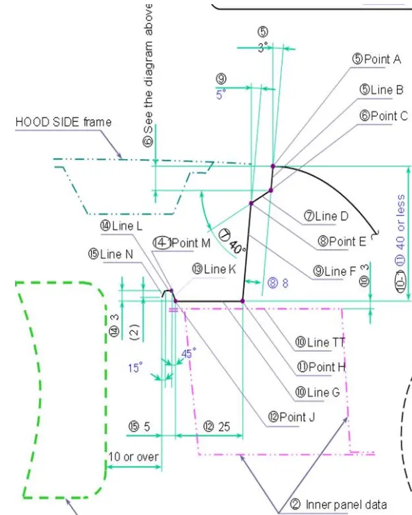
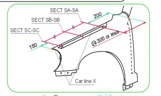
The initial degrees of angle & 9mm length is given so that engine components should not be visible from the outside.
150mm Distance from the front end is kept for the headlamps in the bumper.
200mm Distance from the rear end is kept for the wiper motor assembly.
Steps :
- At first, the edges are extracted and offset to 5mm using a parallel curve.
- Then, two points on the line and two points on the edge(as given in the master section ) are created to have an initial flange.
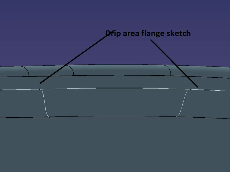
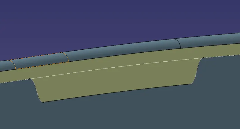
- These two points are split with the line and joined and later extruded in the appropriate direction.
- At last, they are split with the surface to form the flange.
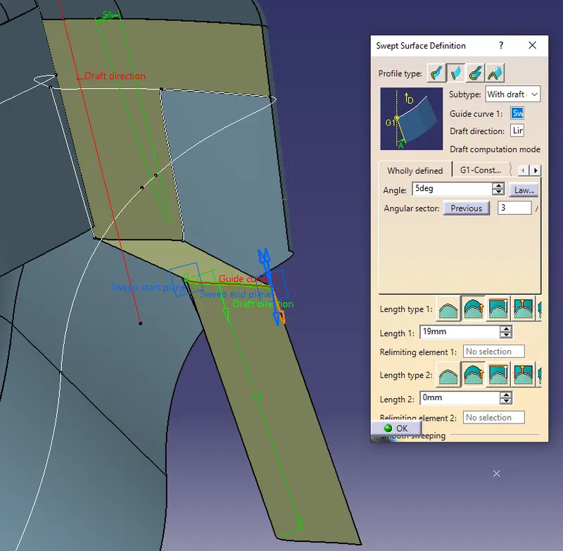
- A line is drawn at the flange surface to be a reference for the draft direction.
- Then rest surfaces are swept at 3 and 5 degrees respectively as shown in the master sketch.
- Appropriate fillets are provided at the sharp corners as shown in the sketch.
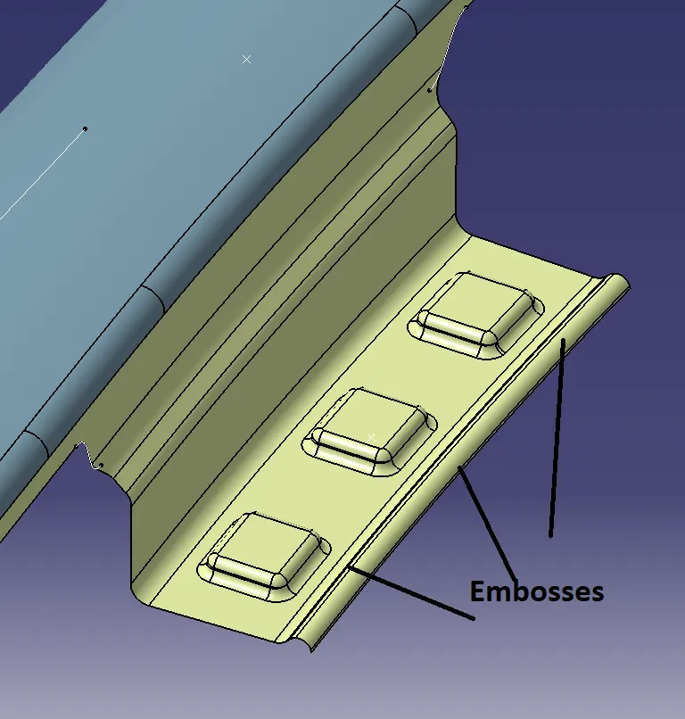
Embosses :
Embosses are provided additional strength to the flanges, since providing holes for the connection is likely to get too weak.
3 holes of size M8 with embosses are provided for connecting the part with the BIW.
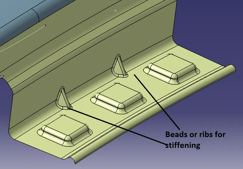
Ribs :
The depth should be around 40mm to 60mm otherwise it causes the spring back effect in the flange. If it is increased beyond the desired, ribs are provided to reduce NVH (but it is wise to provide the small ribs to provide the stiffness to the mountings
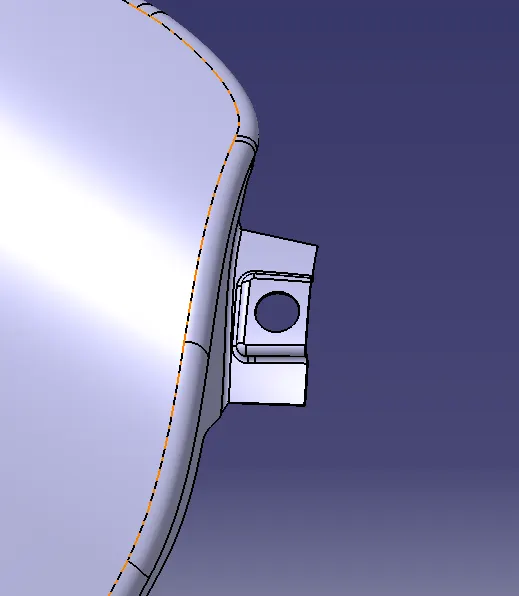
A-pillar mounting:
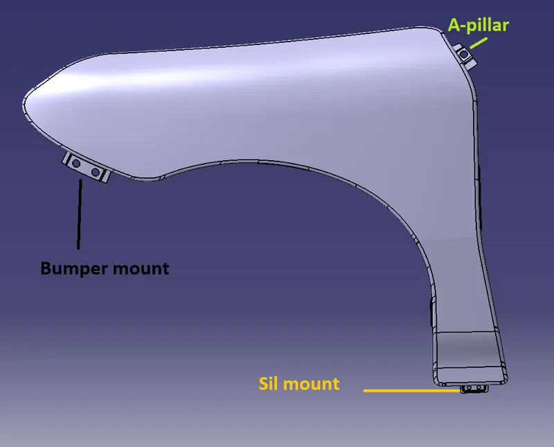
A-pillar mounting is created to join the fender with the A-pillar just around the corner of the front windshield.
M8 hole size with embossment is provided for ease in the attachment and detachment.
Sill mounting :
This is the bottom mounting where the fender is attached with the lower part of the BIW.
Here Two M6 hole is provided for the connection purpose.
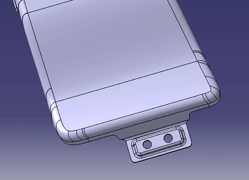
Bumper mounting :
A bumper is a structure attached to or integrated with the front and rear ends of a motor vehicle, to absorb impact in a minor collision, ideally minimizing repair costs.
So the fender mounting for attaching the bumper is created with Two holes,
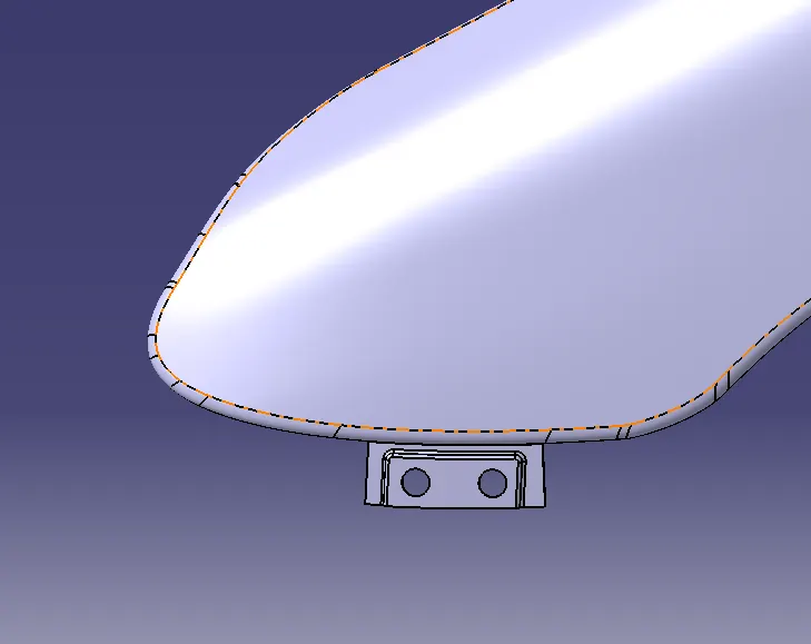
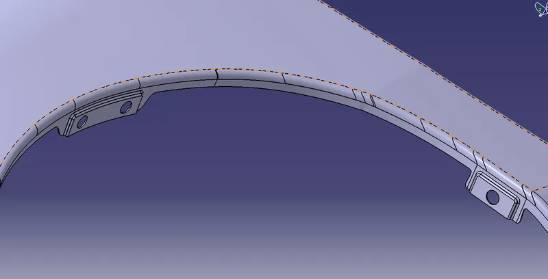
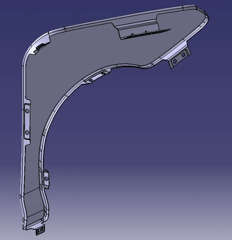
Baffle mounting :
Those are the additional hole provided) to support the accommodation of fender lining in our design. It is a plastic sheet used to cover the metallic part of the fender which acts as a barrier between
the metal fender and foreign bodies to reduce corrosion by sticking foreign bodies on the metal fender. Hence every vehicle is accommodated with a fender ling to reduce the exposure of the fenders to foreign bodies.
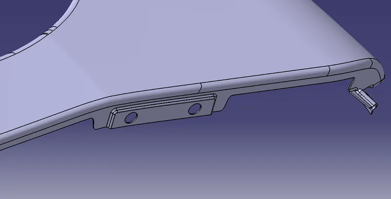
Other than this body mount flange is also created to mount the fender along the hinge of the door.
Results:
Conclusion :
At the end of this project, the fender body was created from the skin. in this fender mounting like a drip, sill and bumper were created following the master sketch to maintain the
look of the final assembly with the Car body.