Fender Design
Title: Design and Mounting Considerations for a Front Fender
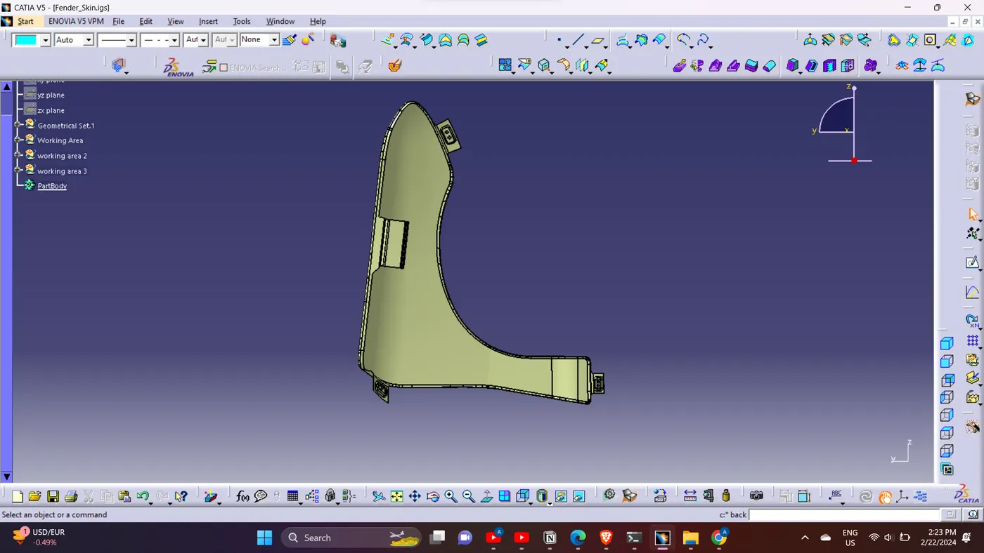
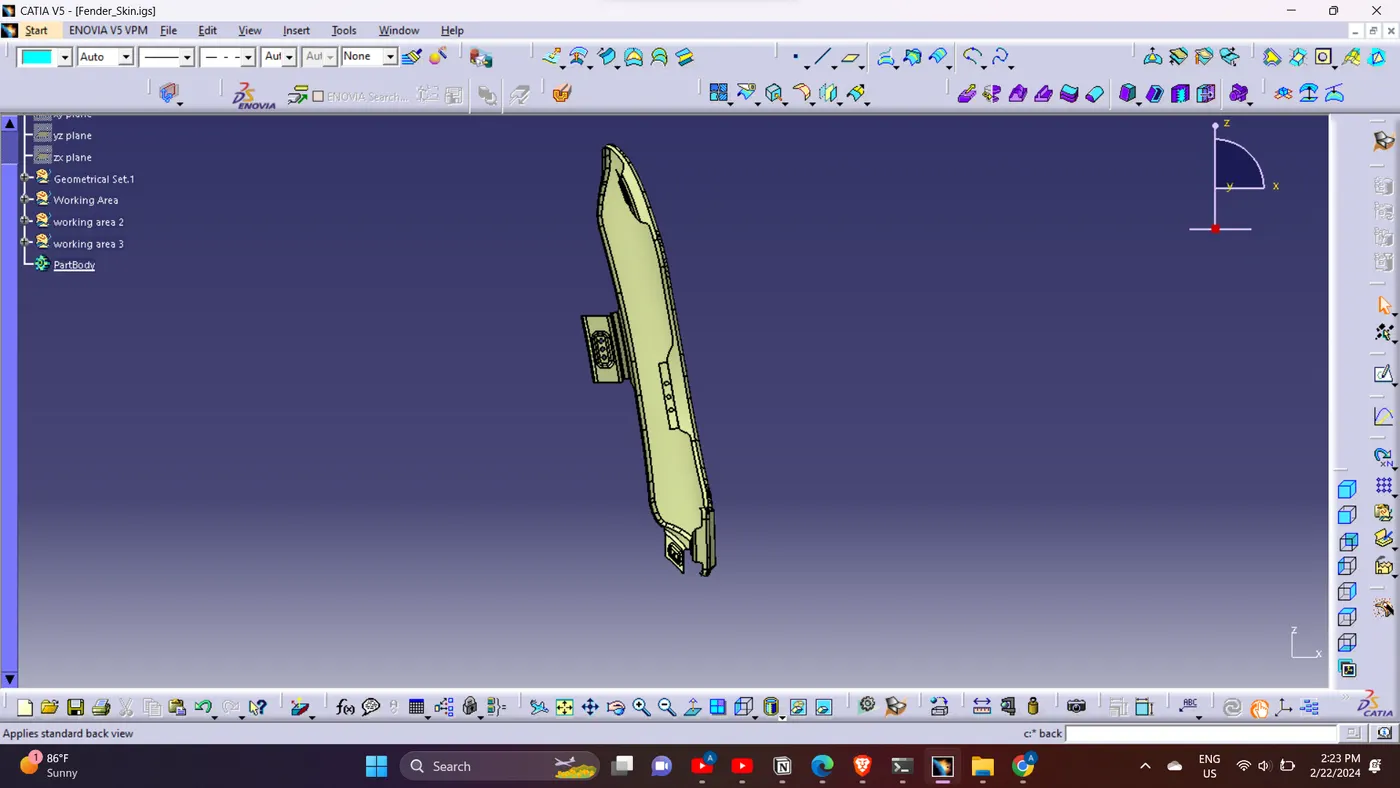
Objective: To develop a front fender design with suitable mountings using a Master Sketch, taking into account safety and manufacturing feasibility for the designated mounting regions, utilizing CATIA software.
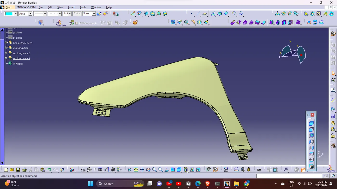
Introduction:
A fender, also known as the wheel well frame in US English, serves the primary purpose of preventing road spray, including sand, mud, rocks, and liquids, from being ejected into the air by the rotating tires of an automobile. This report outlines the design and mounting considerations for a front fender, taking into account safety and manufacturing feasibility.
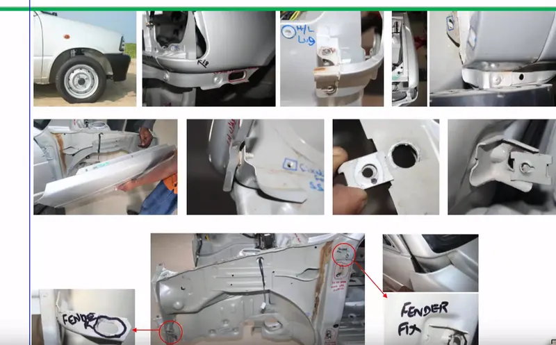
Need for Fender:
1. Protection: Fenders are designed to resist wind, mud, and various roadside particles.
2. Coverage: They provide a protective sheet of metal covering for the car.
3. Corrosion Prevention: Fenders include a plastic component, known as Baffle or Fender Liner, positioned underneath to prevent corrosion by blocking the flow of mud and water.
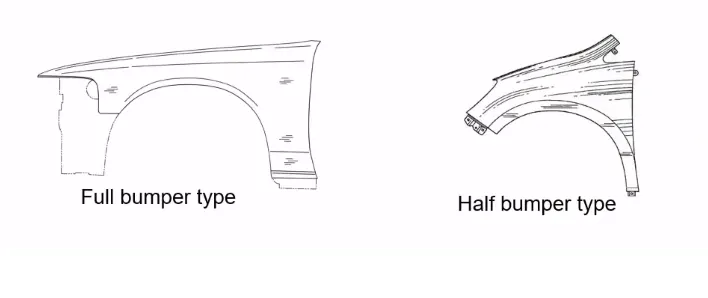
4. Types of Fenders: There are two main types of fenders - Full Bumper Type and Half Bumper Type.
- Full Bumper Type: Less commonly used due to the requirement of a larger blank and increased space occupation.
- Half Bumper Type: Preferred for its efficiency in material use, allowing the production of two fenders simultaneously with minimal raw sheet increase. This type reduces weight and cost.
Design:
Master Sketch:
- Fender Drip Area Section
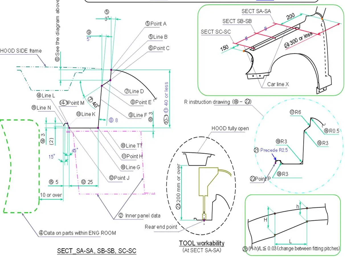
Data Given:
- Drip area specifications, including distances from the front, cowl area, and the engine room.
- Angle and length considerations for the top flange.
- Radius values for the Drip area at different stages.
Mountings:
1. Drip Mounting Area:
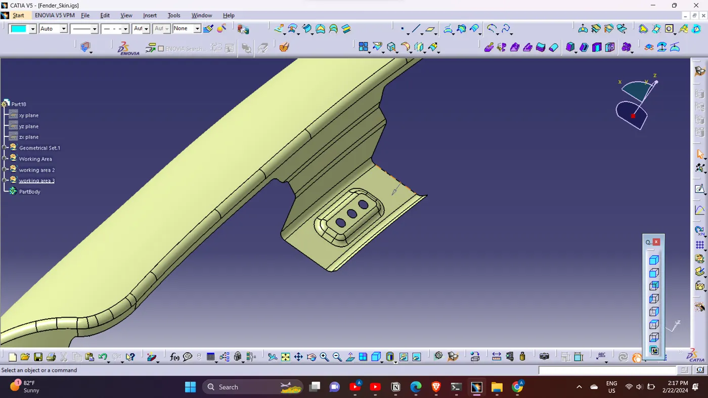
- Positioned to be visible between the hood and fender.
- Attached to the engine compartment.
- Maintains specific distances to prevent springback during manufacturing.
- Drip area should be less than 40mm.
- Embosses on the drip mounting should be flat relative to curvature.
- Dart provided at the edge for increased stiffness.
2. Sill Mounting Area:
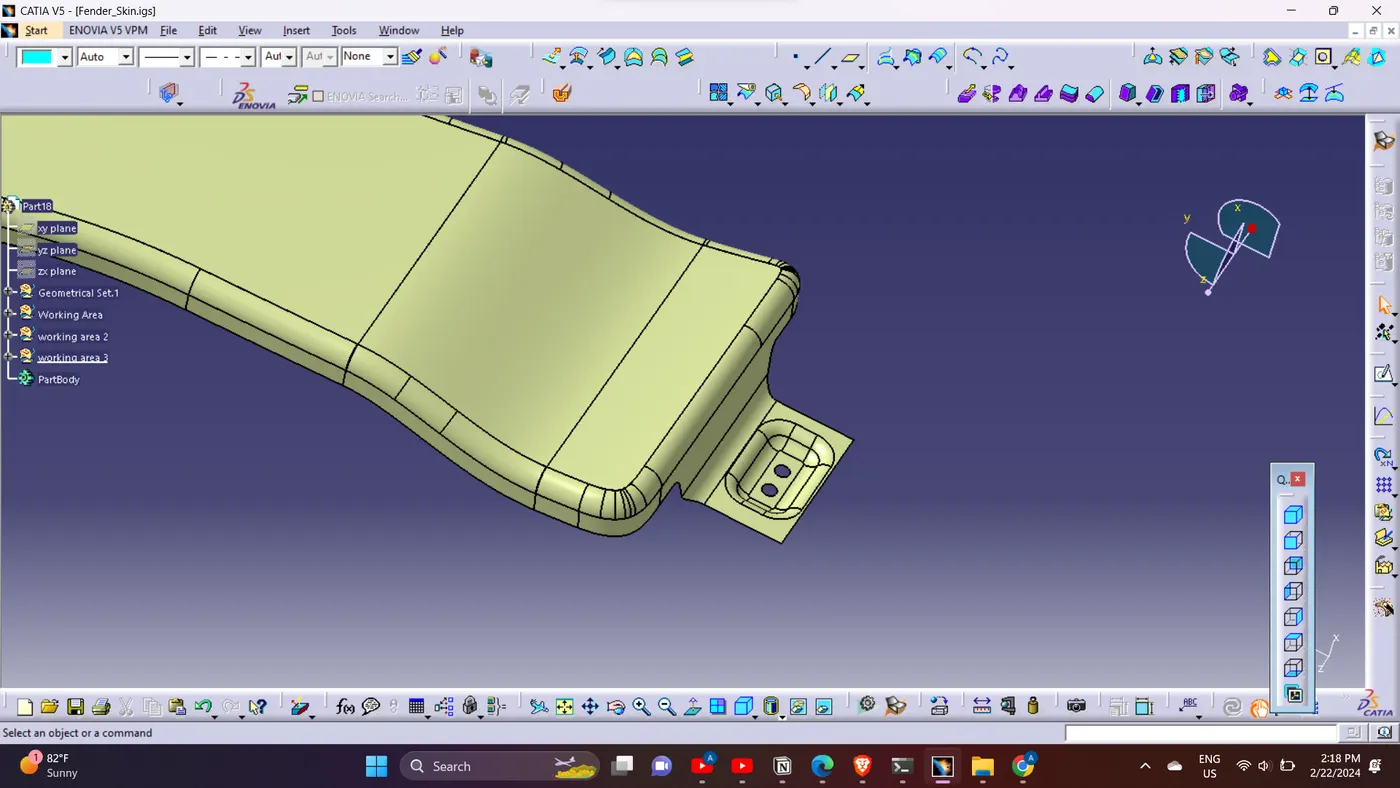
- Placed at the bottom of the fender, fitting firmly to the sill.
- Embosses on the sill mounting should be flat concerning curvature.
3. A-Pillar Mounting Area:
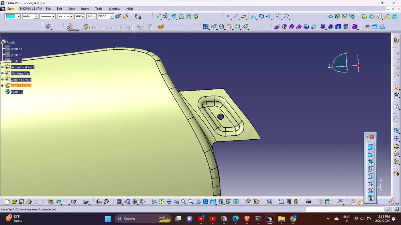
- Located vertically to support the windshield and secure the A-pillar fender.
4. Bumper Mounting Area:
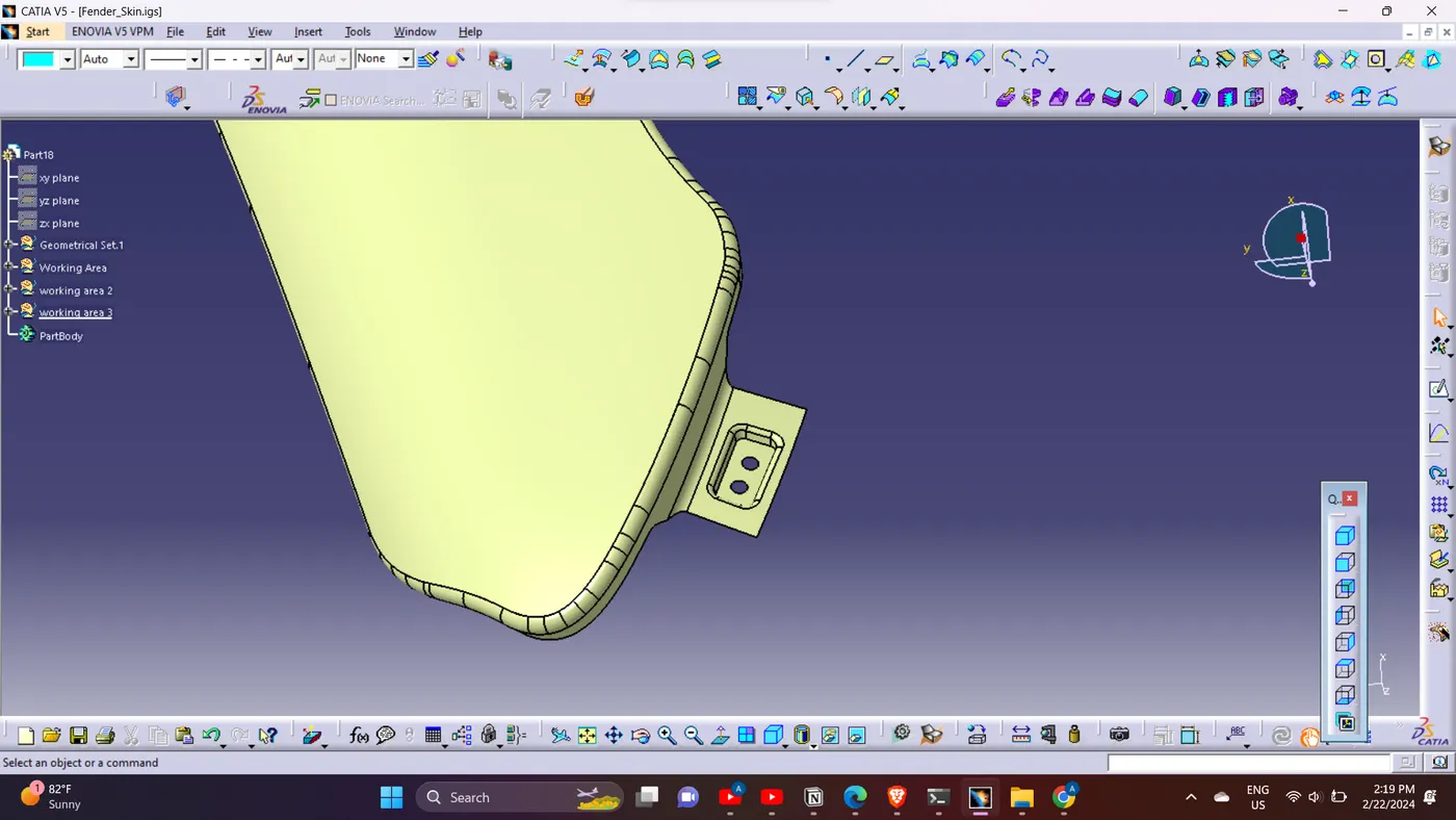
- Positioned at the front to hold the bumper in place.
- Facilitates mounting on the chassis.
5. Baffle or Linear Mounting Area:
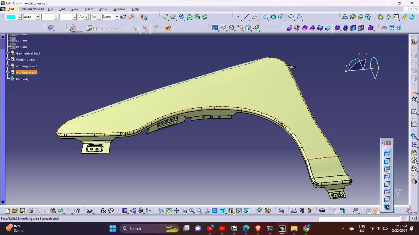
- Baffle mounted on the wheel arch area.
- Plastic unit, called Baffle/Splash Fender Liner, placed to fix the baffle.
Conclusion:
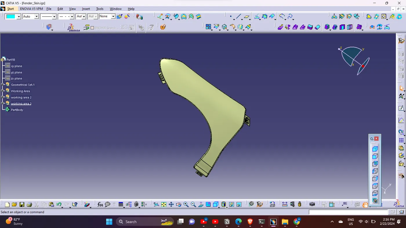
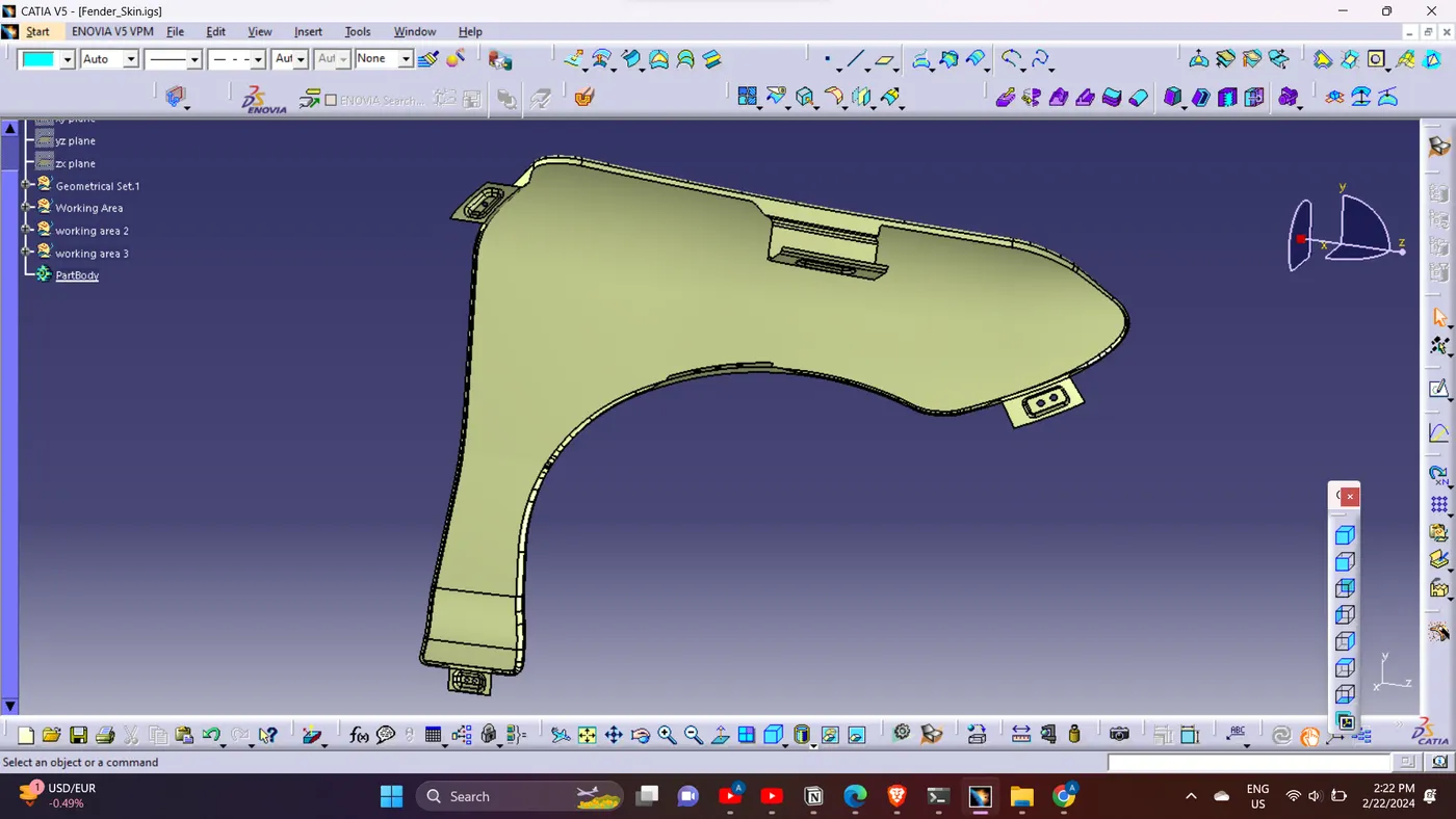
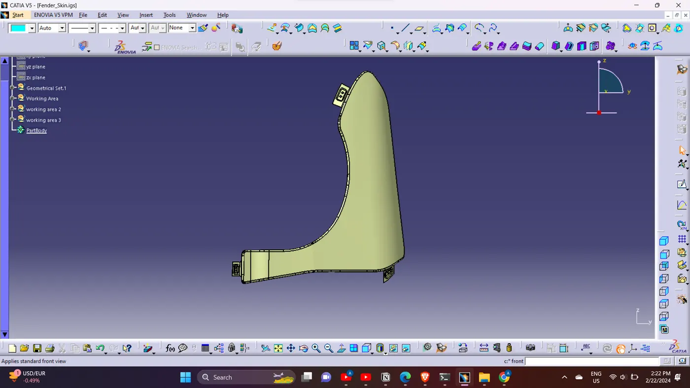
In conclusion, leveraging the CATIA software, we successfully designed the front fender with proper mountings based on the Master Sketch and Design Parameters. This comprehensive approach ensures functionality, safety, and feasibility in the manufacturing process.