Fender Design
FENDER DESIGN:
AIM:
To develop the front fender with its different mounting like A-pillar, drip area, sill, baffle or body mounting and following the design parameters. To create the fender by using Nx Cad.
INTRODUCTION OF FENDER:
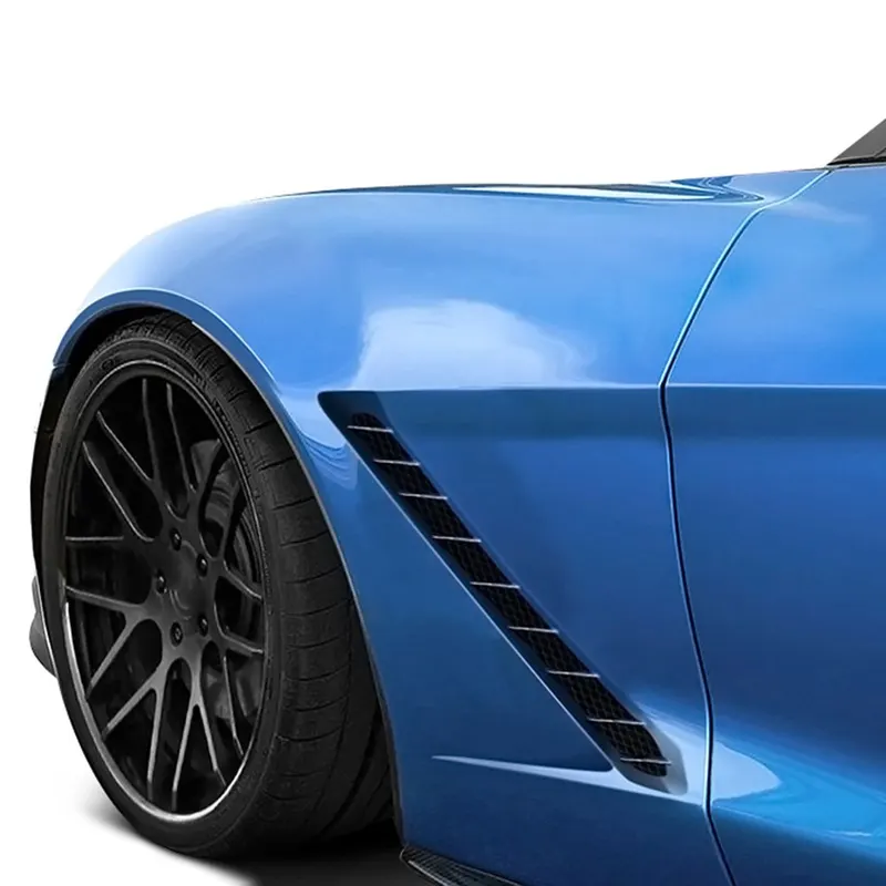
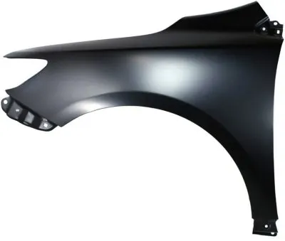
Fender is an aesthetic component or part of a car that frames the wheels. It is a front and rear outer side member of a car which covers the wheel side. Purpose of fender is to prevent sand, mud, rocks, liquids and other particles. Fender is a closing the engine compartment and other compartments. The major role of the fender is to avoid the chipping inside the engine compartment. During the motion the wheel picks a sand mud and small stone particles and throws it inside the car and these fenders will be helpful in preventing them by hitting inside the engine component and car body. It have a plastic part which lies on wheel arch area. It give a role to avoid problems for pedestrian also. The front fenders are separated component where as the rear fenders are integrated with the body sides.
TYPES OF FENDER:
Fender have two types:
- Full bumper type
- Half bumper type
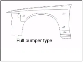
1) FULL BUMPER TYPE:
These types of fenders were used in earlier models of vehicles. They contribute to the major increment of the steel weight by just covering the front headlights with respect to the bumper region. The problem associated with this kind of fender is there is a lot to wastage in the blank and every inch of a material is a cost to the indutry.
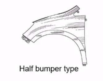
2) HALF BUMPER TYPE:
These fenders are mainly used for serving the purpose of cost cutting and reducing enough proportions of the steel wait rresulting in a reduction of the weight of the vehicle slightly. They can be economically manufactured, i.e by slightly increasing the blank size, we can produce two fenders at a time.
DIFFERENT MOUNTINGS:
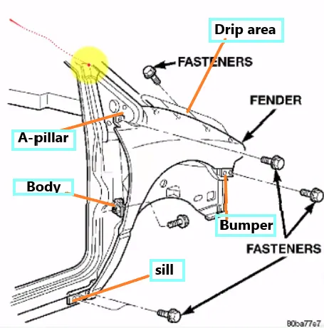
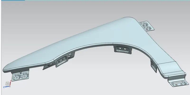
The front fenders have basically five mounting positions with respect to the other components. The mounting positions are as follows;
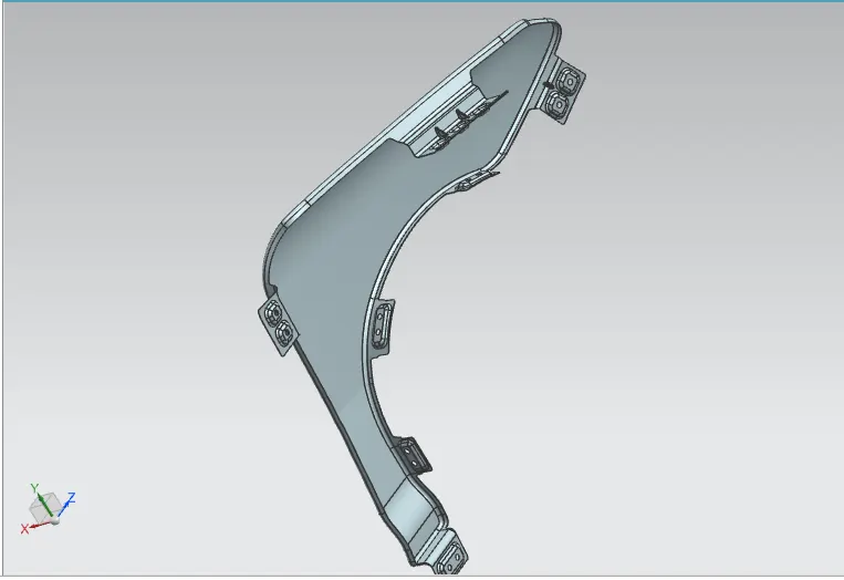
- Drip area mounting
- A-Pillar mounting
- Sill mounting
- Bumper mounting
- Body (Baffle) mounting
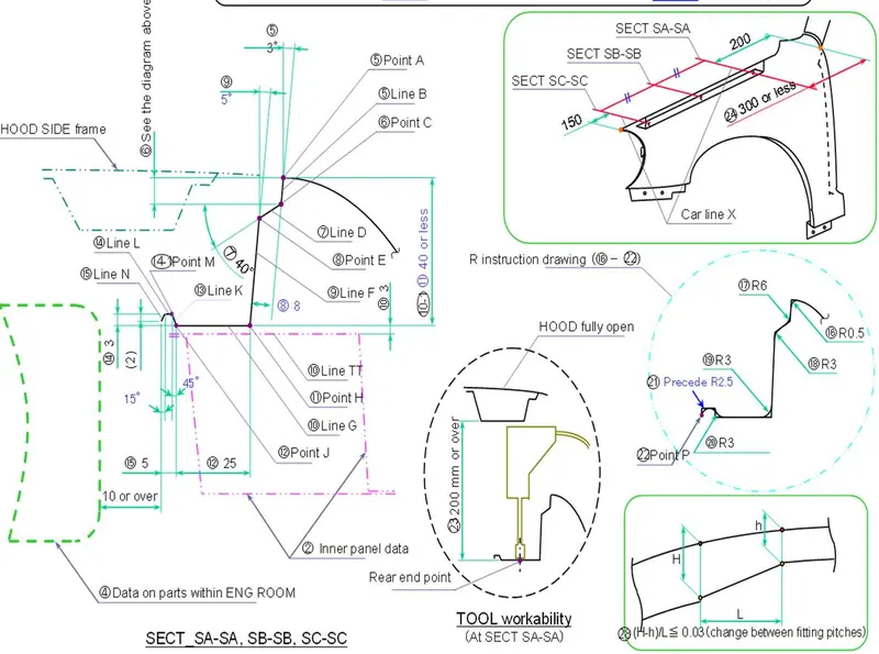
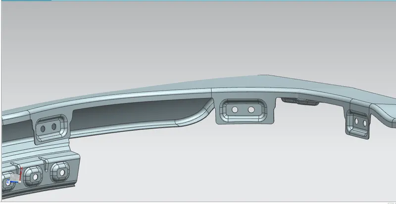
For the creation of the drip area mounting the given master section is followed, and the other mounting points are created by assuming appropriate positions with the respected components.
DESIGN CONSIDERATIONS OF VARIOUS MOUNTINGS:
1) Drip area mounting:
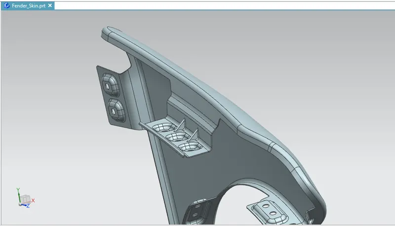
- It is the important mounting unit of the fender. It is connected with the engine compartment, therefore the lot of design constraints are to be followed while designing the fender.
- The drip area should be designed in such a way that it should be atleast 150mm away from the front end of the fender to have sufficient space for mounting headlamps housing.
- Mostly the drip area starts from 200mm away from the rear end of the fender to have sufficient space for the cowl which carries the wiper equipment.
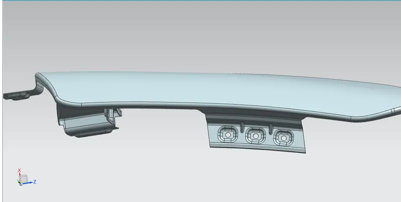
- Two darts are added on the longer side of the drip area in order to provide the stiffness and adds strength to the part. This helps to the fender not to vibrate and impact the forces outside of the fender during motion of the vehicle.
- The length of the drip area is less than the 40mm, this is avoid the spring back effect during the manufacturing process. Embosses are provided on the mounting to strengthen them during fastening.
2) A-PILLAR MOUNTING:
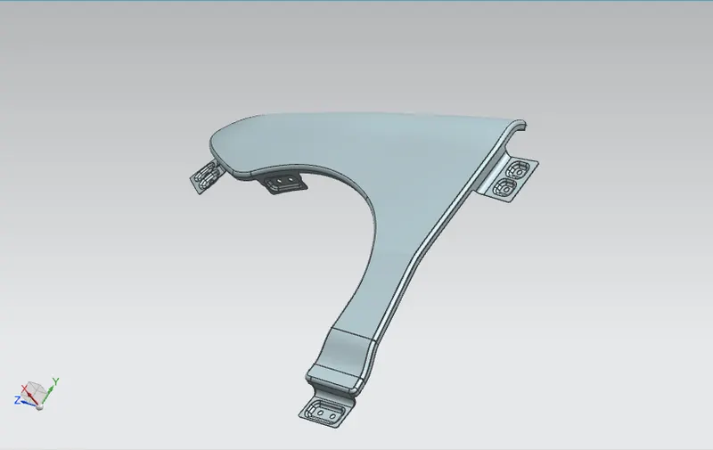
This mounting position is created for attaching the fender to A-pilar of the vehicle. The mounting has to be created by taking the reference from the A-pillar of the vehicle. Enough clearance should be given for the easy mounting of the wiper equipment.
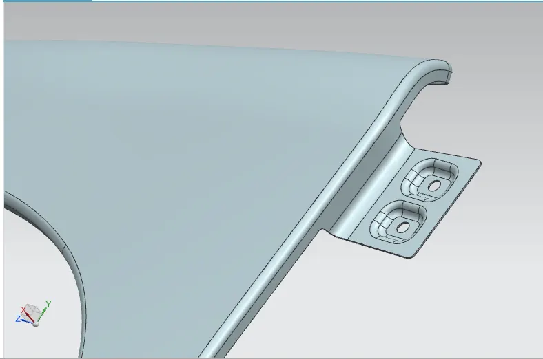
3) SILL MOUNTING:
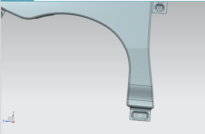
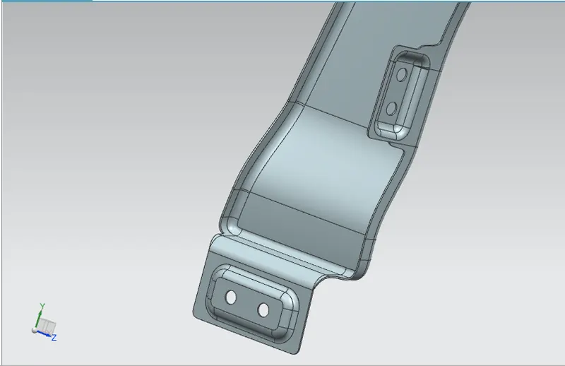
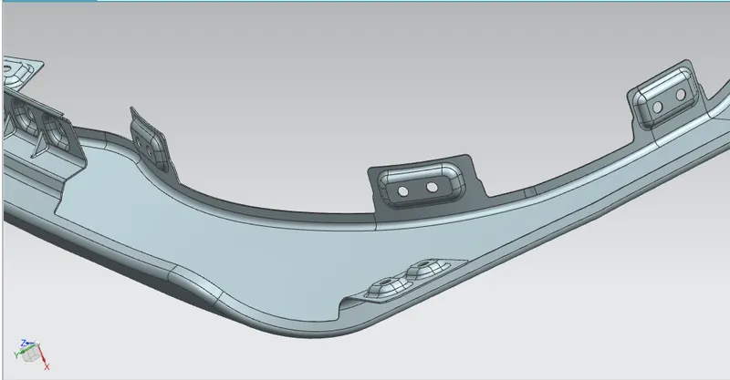
Sill is the panel directly below the bottom of the door supporting the floor and may be used to combine the floor and the body. The bottom end of the fender is mounted on the sill body for reinforcement of the fender panel, thus the sill mounting position is designed with holes and emboss.
4) BUMPER MOUNTING:
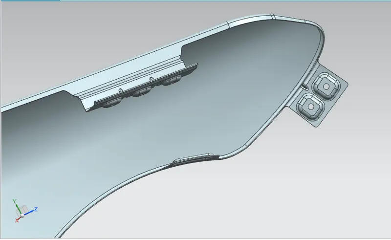
This mounting point is created for attaching the bumper to the fender. It should have enough strength to hold the bumper steadily.
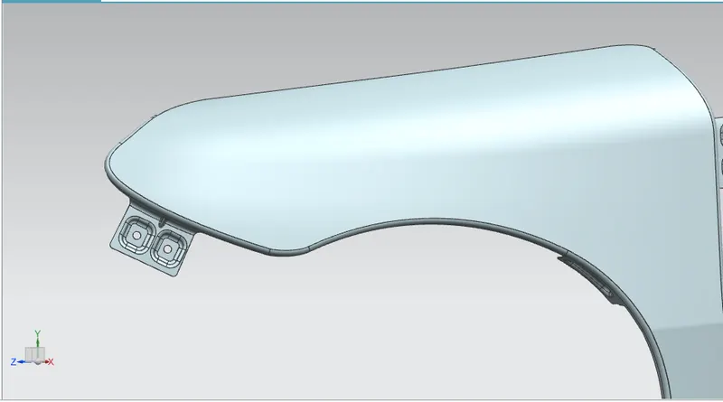
5) BAFFLE MOUNTING:
These mounting points are created for attaching plastic components baffle which prevents chipping inside the engine compartment. It protects the car engine compartment and pedestrians from causing inuries from chipout debris on the road when the car is in motion.
MANUFACTURING PROCESS:
Purpose of fender is prevent rocks, mud, sand, liquids from being thrown into the air or on to the pedestrians by a rotating wheel fender is made aerodynamic in shape to reduce the air drag.
Manufacturing process of the fender majorly involves these operations;
- Embossing
- Bending
- Cutting and Blanking
1) EMBOSSING:
Embossing is a metal forming process for producing raised or sunken designs or relief in sheet material using matched male and female roller dies, theoretically with no change in metal thickness or bypassing sheet or a strip of metal between rolls of the desired pattern.
2) BENDING:
Metal bending is a proccess by which metal can be deformed when applying force to the subject, which causes it to bend at an angle and form the anticipated shape which often results in it being in a 'V' or 'U' shape. This is done through the application of force on a workpiece. The force on the work piece can be mechanical, pneumatic or hydraulic.
3) CUTTING AND BLANKING:
Cutting processes are those in which a piece of sheet metal is separated by applying a great enough shearing force to cause the material to fail.
Blanking is a steel manufacturing process in which a flat, geometric shape is created by feeding a coil of sheet metal into a press and die in this process, the blank is punched out from the large metal sheet.
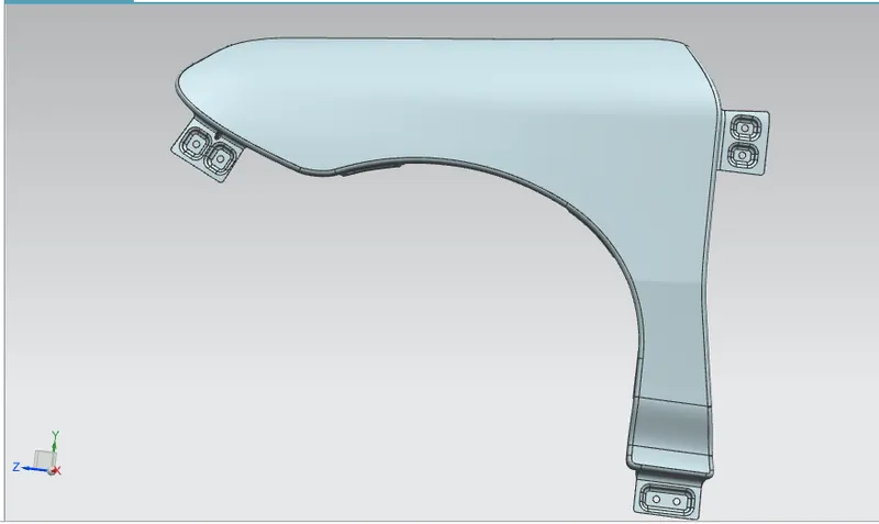
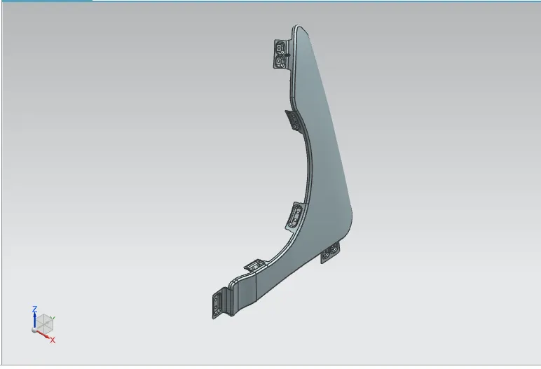
VARIOUS VIEWS OF FENDER COMPONENT: