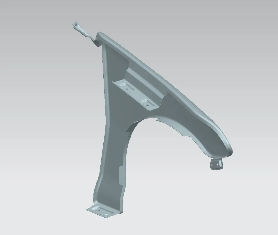
Fender Design
Fender Design
PROJECT OBJECTIVE:
The primary goal of this project is to acquire proficiency in utilizing fundamental tools, commands, and surface modeling techniques within Siemens NX CAD. The specific focus is on designing a fender for a given model. This involves employing the Master sketch approach while accounting for safety considerations and manufacturability factors, particularly in the potential mounting areas.
The project entails the following key tasks:
-
-
Design of Drip Area
-
Design of Sill Mount Area
-
Design of Body Mount Area
-
Design of Bumper Mount Region and A-pillar Mount Region
- Design of A-pillar Mount Region
-
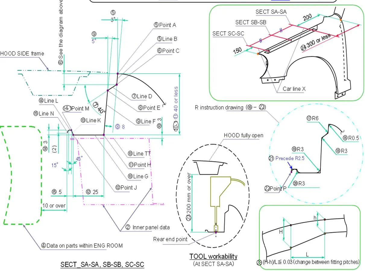
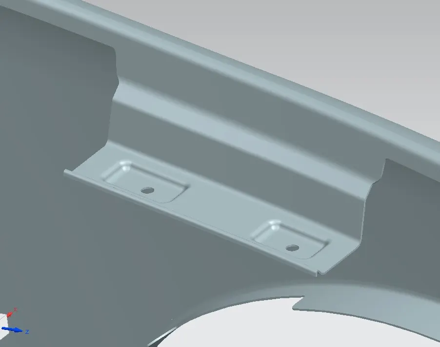
Drip Mounting Area - In the beginning steps of designing the fender, we create a spot called the drip mounting area. This area is really important and needs specific qualities to meet the basic requirements of the fender's design. Even though we're doing things a bit differently from the usual approach, you can still spot the drip area by looking at the space between the fender and the hood. Other attachment points are hidden behind different parts.
Procedure:
- By utilizing the data in the master section gave the dribble mounting was made.
- The drip area would be recognizable from the opening between Hood and Fender.
- This mounting is attached to the engine compartment of the car.
- A min 150mm distance is kept from the front side and a distance 300mm or less can be kept on the rear side.
- At that point, the excess undesirable parts were trimmed out.
- This is to avoid the spring back during the manufacturing. the edge of the mounting should at least 10mm away from any nearby component in the engine.
- The drip area should be less than 40mm.
- The embosses that are created on the drip mounting should be flat with respect to the curvature.
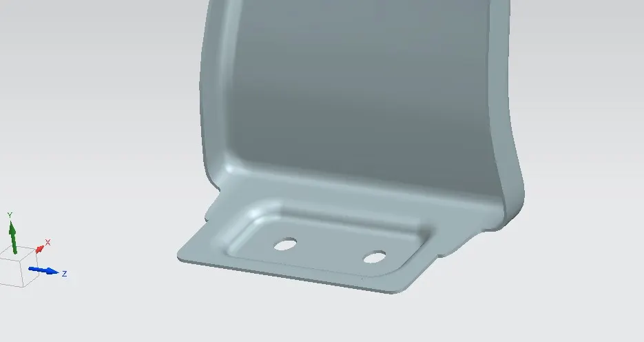
Sill Mounting Area - An automobile is designed with wide openings to accommodate doorways on different sides of its body. Because the vehicle body experiences various externally applied forces like vertical curves and longitudinal twists that act around the body's axis of rotation, it's important that the parts of the vehicle body containing the door openings, particularly the lower portions, have enough strength. This need is often fulfilled by using side frames located at the lower right and left sections of the vehicle body to connect its longitudinal direction. These side frames serve as supports to maintain the body's structural integrity around the door openings.
Procedure:
- To create the Sill Mounting, excess flanges were trimmed.
- Next, a reference point was established, and the required sketch was drawn.
- The sill mounting was achieved by extending the flange in the sill area.
- After extending the flange, holes were added to serve as mountings.
- Additional strength was added by creating embossed features at the hole mounting locations.
A-Pillar Mounting Area:
Pillars serve as vertical supports in a vehicle, positioned around all the windows. They play a crucial role in securing the glass and contributing to the overall structural stability of the vehicle, especially the roof. The "A" pillar, specifically, holds the windshield securely. Moving along, the "B" pillars come after the front doors, typically providing significant structural support for the vehicle's roof.
Procedure:
- To commence, remove the surface information provided by the styling group.
- Next, the outer edge of the fender was inwardly offset to a specific distance.
- By employing the "bend on surface" command, the undesired portions were trimmed using the "trim sheet" function.
- Leveraging the "law extension," the A-Pillar was extended and then trimmed on its sides to achieve a flat edge.
- To facilitate the creation of embosses intended for fender-A-Pillar attachment, establish a datum plane.
- Proceed with drawing the necessary sketch on the datum plane.
- Implement "face blend" and "edge blend" to incorporate the essential blends as needed.
Bumper Mounting Area: A bumper is a framework affixed to the front and rear portions of a vehicle, serving to absorb the force of minor collisions and ideally reducing repair expenses. As a result, the area where the bumper is secured involves an additional part of the fender that covers the splashing region. This often takes the form of a half-fender design. Bumpers are now designed with pedestrian safety in mind, using flexible materials for bumper covers to minimize harm in case of vehicle-pedestrian collisions. Specifically, front bumpers are crafted from softer materials like foams and crushable plastics, with lowered profiles to lessen the impact's severity on pedestrians' legs.
Procedure:
- Undesirable sections were eliminated using the "Curve on Surface" and "Trim Surface" commands.
- To create a level embossed surface, a datum plane was established. Following this, the essential sketch was drawn on the datum plane and the required embossed feature was fashioned.
- After forming the embosses, holes were trimmed using the "Trim Sheet" command. These 5mm holes were effectively removed.
- Concluding the process, the necessary "Face Blend" and "Edge Blend" techniques were employed.