FENDER DESIGN
OBJECTIVE: The objective of this project is to design the front fender of a car using NX CAD software, incorporating various mounting features such as Drip Area Mounting, Sill Mounting, Bumper Mounting, A-Pillar Mounting, and Baffle Mounting. Utilizing the provided initial surface and Master section for the Drip Area Mounting creation as a reference point, the aim is to develop a robust and efficient design that aligns with engineering standards learned during academic studies.
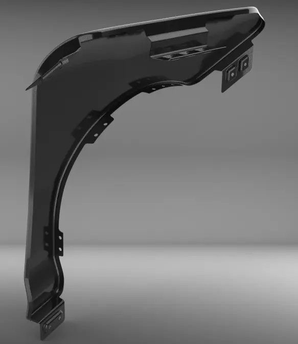
- We are utilizing NX CAD software to create an innovative and functional front-fender design.
- Incorporating mounting features like Drip Area Mounting, Sill Mounting, Bumper Mounting, A-Pillar Mounting, and Baffle Mountings in accordance with engineering standards.
- We are adhering to prescribed guidelines while ensuring structural integrity, safety, and aesthetic appeal.
- Applying appropriate engineering principles to optimize performance, facilitate assembly processes, and meet industry requirements.
- We are demonstrating proficiency in utilizing the Master section of Drip AreaMountings while employing individual creativity within established engineering standards.
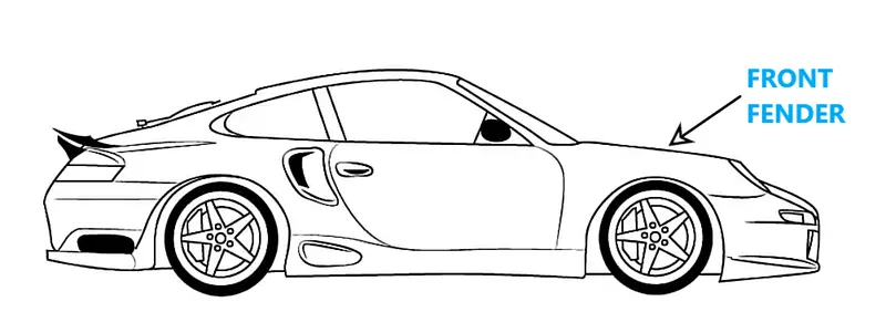

- WHEEL WELL AREA: Refers more broadly to the internal cavity surrounding wheels within a vehicle.
- WHEEL ARCH: Specifically denotes the visible exterior opening framing each individual wheel on a vehicle’s body panels.

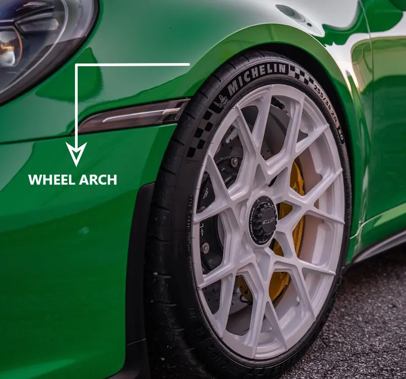
1. SIZE & COVERAGE: Full fenders are larger in size compared to half fenders. They provide complete coverage over the entire wheel well area, extending from the top of the tire all the way down towards the lower body panels.
2. PROTECTION: Full fenders offer comprehensive protection against debris, water, mud, rocks, and other road contaminants that can potentially damage both mechanical components (such as suspension systems) and exterior body panels.
3. AESTHETIC CONSIDERATIONS: Full fenders contribute significantly to defining a vehicle's appearance by adding visual bulkiness or sleekness based on design language.
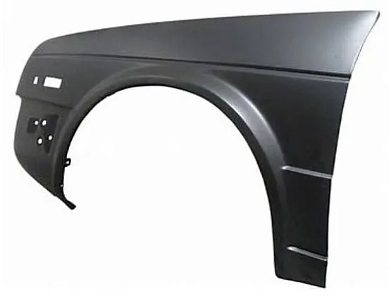
1. SIZE & COVERAGE: Half fenders are smaller than full ones; they cover only a portion of the wheel well area rather than extending all the way down towards lower body panels.
2. MATERIAL EFFICIENCY: The use of half-fender designs allows for optimized utilization of sheet metal blanks during manufacturing processes because it reduces material wastage compared to full-fender designs.
3. WEIGHT REDUCTION: Due to their reduced size, half-fender designs typically weigh less than full ones. This weight reduction contributes positively towards improving fuel economy & overall vehicle performance.
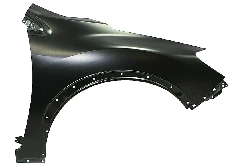
- FULL FENDER USUAGE: In most conventional passenger cars or luxury vehicles where aesthetics play a significant role alongside functionality. Full Fender designs may be preferred due to their comprehensive protection features while maintaining an appealing appearance.
- HALF-FENDER USUAGE: In certain applications such as compact cars, sportier models, racing vehicles, and off-road vehicles where weight reduction, fuel efficiency,& agility take precedence over complete protection. Half-fender designs can be utilized to reduce weight & improve performance.
2. DRIVING CONDITIONS:
- FULL FENDER USUAGE: In areas where road conditions are unpredictable, there is a higher risk of encountering debris, mud, or gravel. Full fenders provide enhanced protection against potential damage from these hazards.
- HALF-FENDER USUAGE:: In controlled environments such as racetracks or well-maintained roads with minimal debris presence. Half fenders may offer sufficient protection while reducing weight for improved handling and performance.
3. DESIGN INTENT:
- FULL FENDER USUAGE When the design objective prioritizes a traditional or muscular aesthetic appeal. Full fenders contribute to the desired visual impact by adding bulkiness and contour lines that define the vehicle's overall appearance.
- HALF-FENDER USUAGE: When the design intent focuses on achieving a sleeker or sportier look. Half fenders allow for more streamlined body profiles without compromising aerodynamic efficiency.
- STRUCTURAL INTEGRITY: The Drip Area Mounting plays a crucial role in maintaining the overall rigidity and strength of both the fender and adjacent body panels.
- AESTHETIC INTEGRATION: Properly designed Drip Area Mountings contribute to seamless integration between different body parts, enhancing visual appeal by creating smooth lines and contours.
2. SILL MOUNTING: The Sill Mounting involves attaching or integrating the lower section of the fender with other components like rocker panels or side skirts. It provides additional reinforcement, stability, and protection for this vulnerable area against impacts from road debris or curbs.
- IMPACT RESISTANCE: The Sill Mounting helps absorb or distribute energy during minor collisions or contact with objects at ground level, minimizing damage to both the fender and surrounding areas.
- IMPROVED AERODYNAMICS: A well-designed Sill Mounting contributes to reducing drag by ensuring smooth airflow around wheel wells, improving vehicle efficiency.
- STRUCTURAL SUPPORT: Bumper mountings reinforce connection points between bumpers and fenders, to sustainability & integrity during minor impacts.
- CRASH ENERGY MANAGEMENT: In case of an accident, the bumper mounting system aids in absorbing and dissipating impact energy to protect both the fender and occupants.
- STRUCTURAL INTEGRITY: The A-Pillar Mounting ensures that forces acting on the fender are correctly distributed through its connection with the rigid A-pillar structure.
- CRASHWORTHINESS: Properly designed mountings contribute to maintaining occupant safety during frontal collisions by effectively transferring impact loads away from critical areas.
- AERODYNAMIC EFFICIENCY: By properly securing baffles within the fender assembly using robust mountings, it helps optimize airflow patterns around wheels, reducing drag & enhancing overall vehicle aerodynamics.
- NOISE REDUCTION: Effective baffle mounting reduces unwanted noise caused by turbulent airflow inside wheel wells, resulting in improved ride comfort&acoustic performance.
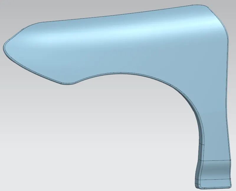
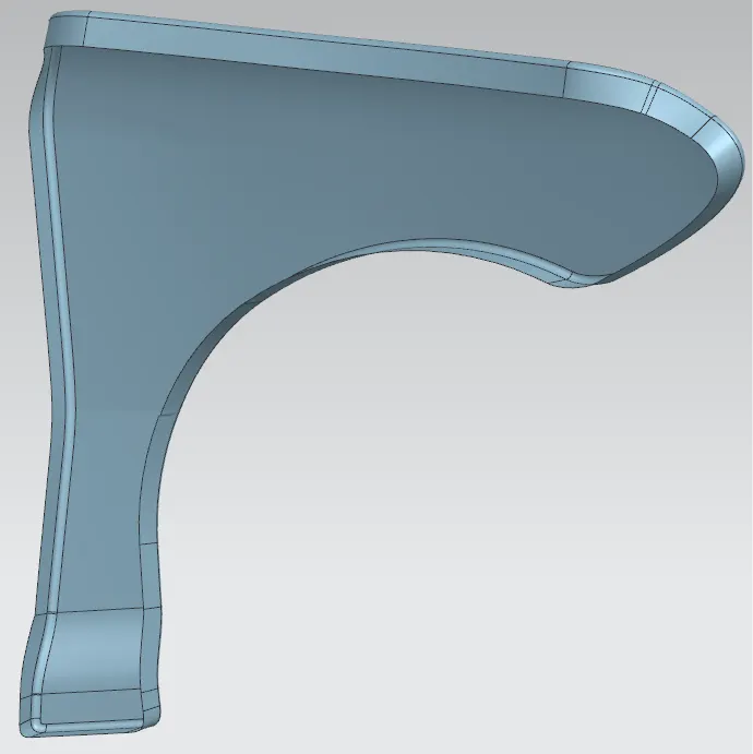
1. Importing Skin Data into NX: To initiate the design process, it is essential to import the skin data of the fender into NX as a ".prt" file. By importing this data accurately into the software environment, we can establish a foundation upon which to build our mountings with precision.
2. Creating A-Pillar Mount:
By conducting a meticulous analysis of the surface geometry, taking into account alignment requirements and aesthetic integration with adjacent components, we can effectively define precise boundaries using the "Curve on Surface Command." This allows us to establish robust connections between critical elements.
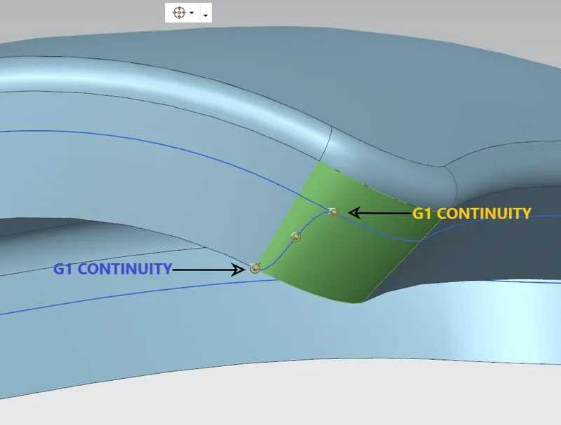
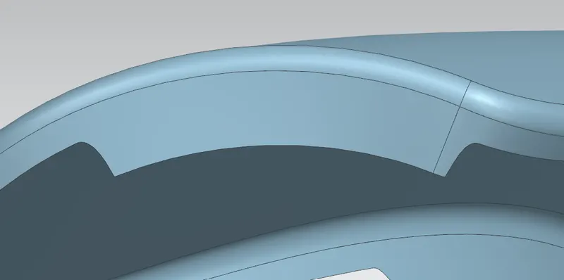
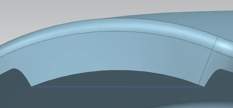
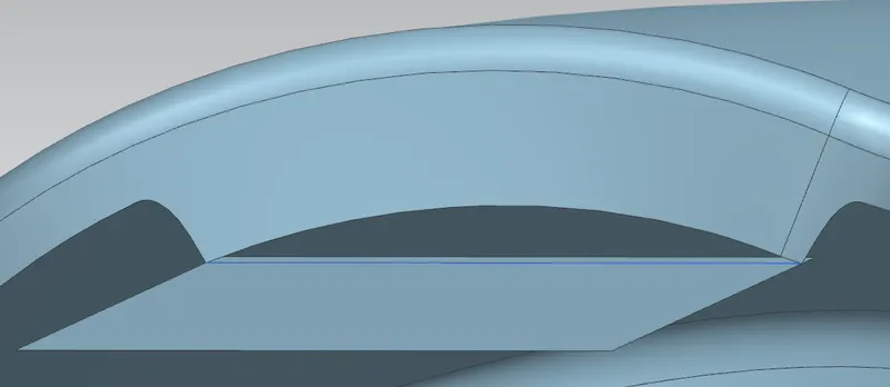
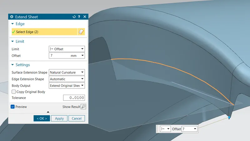
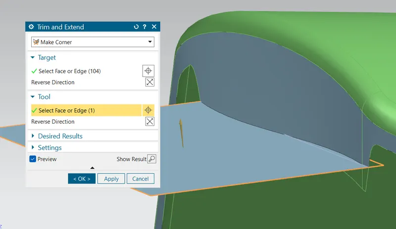
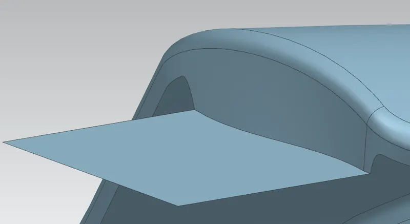
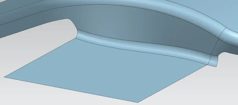
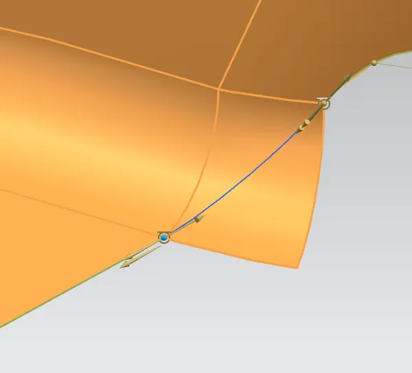
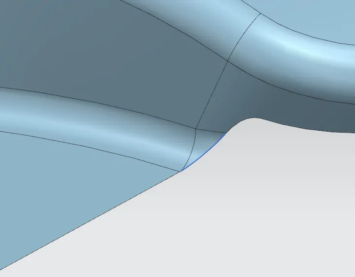
To establish proper orientation and reference for subsequent operations, a Datum Plane will be created using the "Curves and Points" option within the Datum Plane creation module. By selecting three points strategically positioned in relation to our desired design parameters, we can accurately define this essential datum plane.
Using this newly created datum plane as a reference framework, we proceed to sketch both the embossed region and hole for fastener placement. Adhering to best practices in sketching techniques within NX CAD software, such as dimensioning constraints and geometric relationships among entities, ensures optimal control over our design intentions.
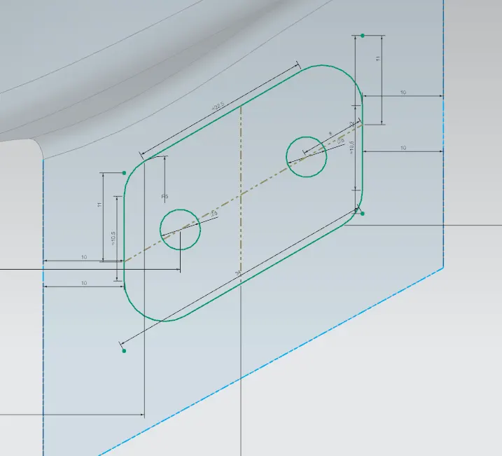
Once fully constrained and validated against relevant specifications or standards, the sketched elements are projected onto their designated target surfaces. The projection process aids in precisely defining their positions while maintaining necessary alignments with existing geometry.
To materialize the embossed region per our design requirements, NX CAD's versatile 'Emboss' command is employed. By specifying appropriate parameters, such as depth or shape characteristics, this command facilitates the seamless creation of raised regions directly on selected surfaces. This feature adds depth, dimension, and visual interest to the overall Fender mount design while ensuring compatibility with adjacent components and assembly requirements.
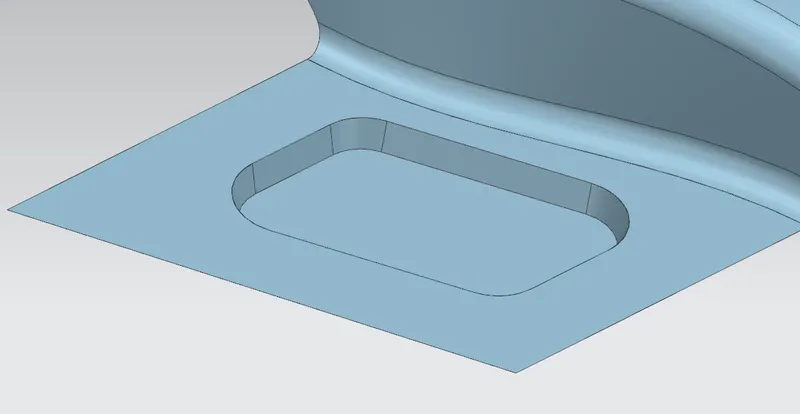
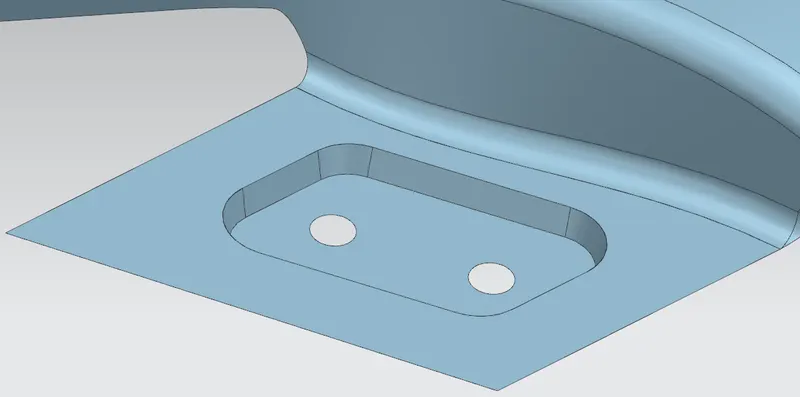
Finally, to achieve aesthetically pleasing transitions between various regions and edges of the fender mounts, 'Face Blend' and 'Edge Blend' commands are used. These commands allow for the creation of smooth transitions and fillets between adjacent faces and edges, respectively. By accurately defining blend radii or profiles, we ensure that the resulting blends meet design intent specifications while optimizing functionality and visual appeal.
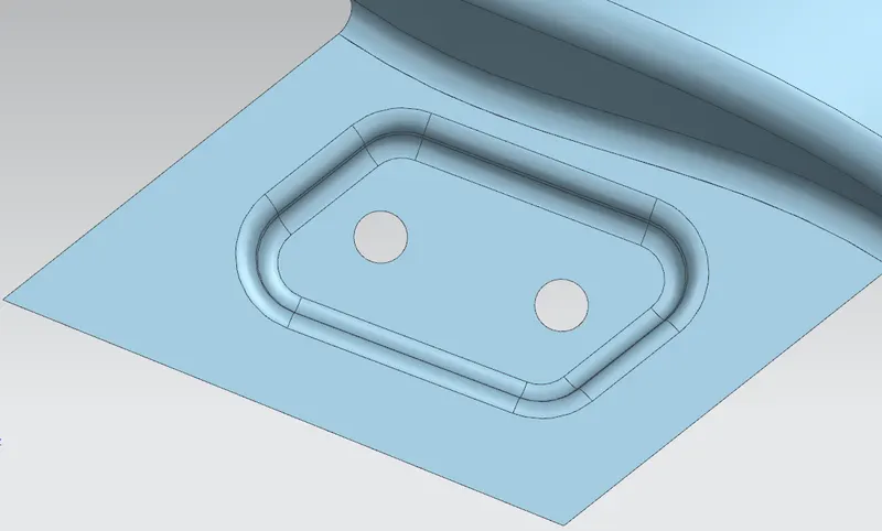
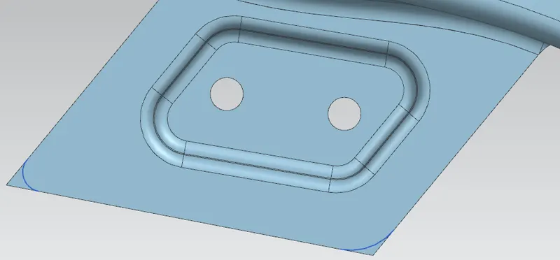
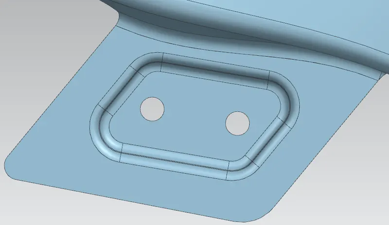
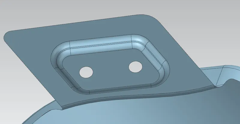
In summary, by carefully analyzing surface geometry, utilizing commands like 'Curve on Surface,' 'Law Extension,' 'Datum Plane Creation' with point selection, sketching techniques for the embossed region and hole creation, projection onto designated surfaces, and employing commands such as 'Emboss,' 'Face Blend,' and 'Edge Blend', we can create fender mounting surfaces that exhibit precise connections, functionality, aesthetics, and structural integrity essential to automotive design.
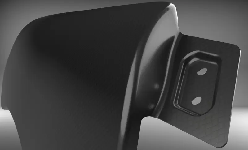
3. Drip Area Mount Creation: Following the successful completion of the A-pillar mount design phase within NX CAD software, the focus shifts towards creating an effective Drip Area Mount. Understanding the importance of alignment and stability in this region, we make use of NX CAD’s advanced tools and features for exact curvature matching and surface creation. These include G1 continuity controls to ensure seamless integration between the fender top panel and adjacent body structures. This step ensures proper fitment while enhancing both functionality and aesthetics related to the Fender design.
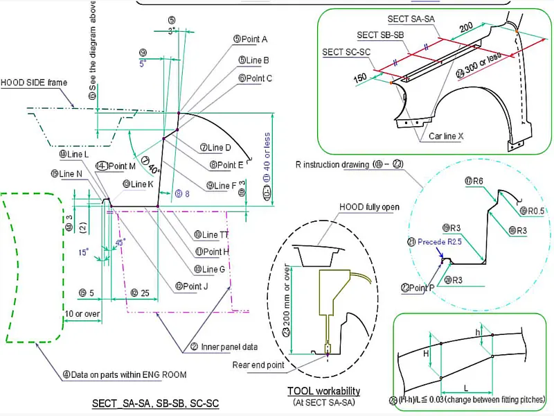

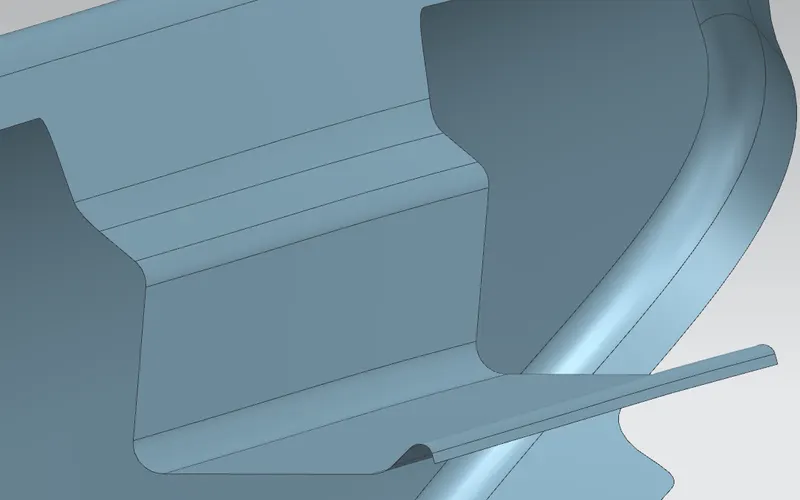
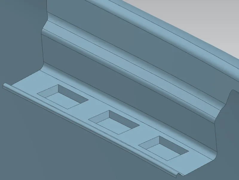
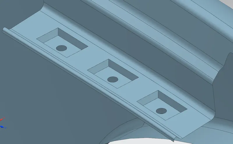
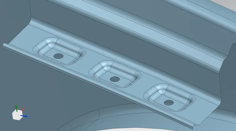
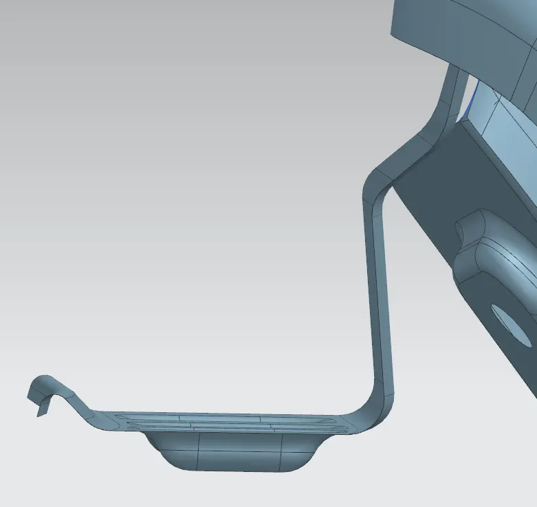
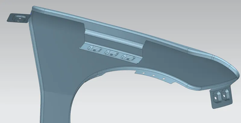
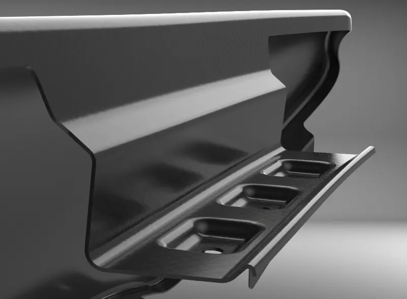
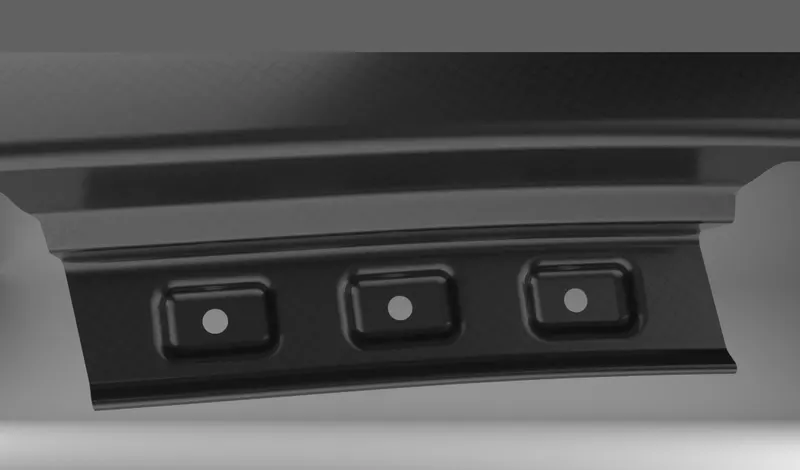
4. Bumper Mount Development: With the A-Pillar and Drip Area mounts established, attention turns to designing a reliable Bumper Mounting system. Utilizing NX CAD's comprehensive toolset, we can create precise connection points between the fender and bumper structure. These connections must be engineered to ensure solid attachment and safeguard against low-speed impacts. Extensive analysis of load paths, distribution, and crash energy management is undertaken to optimize both functionality and safety within this critical area.
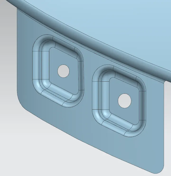
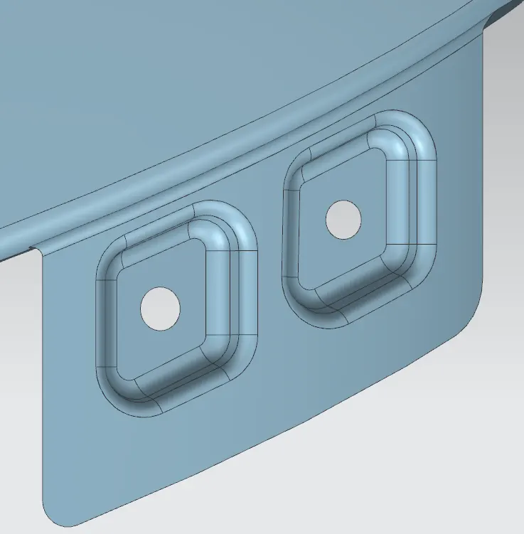
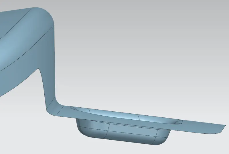
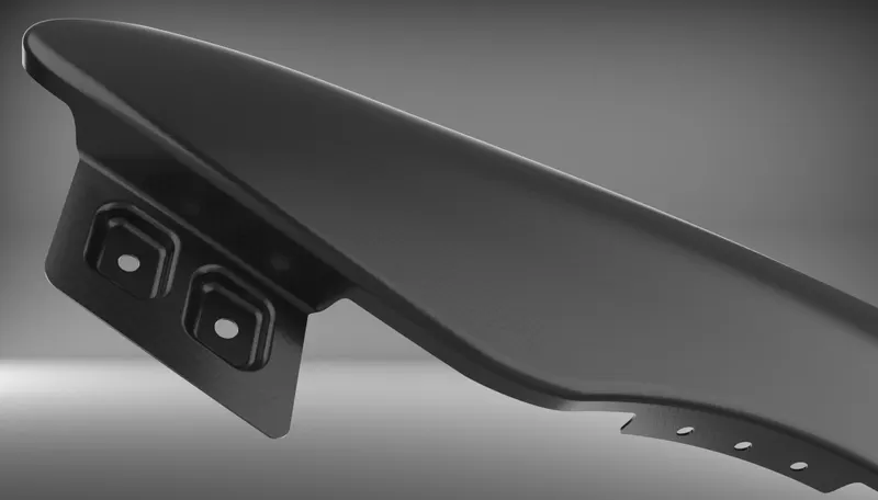
5. Sill Mount Integration: To reinforce the lower section of the fender, a well-designed Sill Mount is crucial. This mount enhances stability and protection against potential hazards encountered at ground level. During this stage in NX CAD software, we focus on seamlessly integrating mounting points with rocker panels or side skirts. The aim is to establish robust connections that withstand impact forces while complementing surrounding design elements.
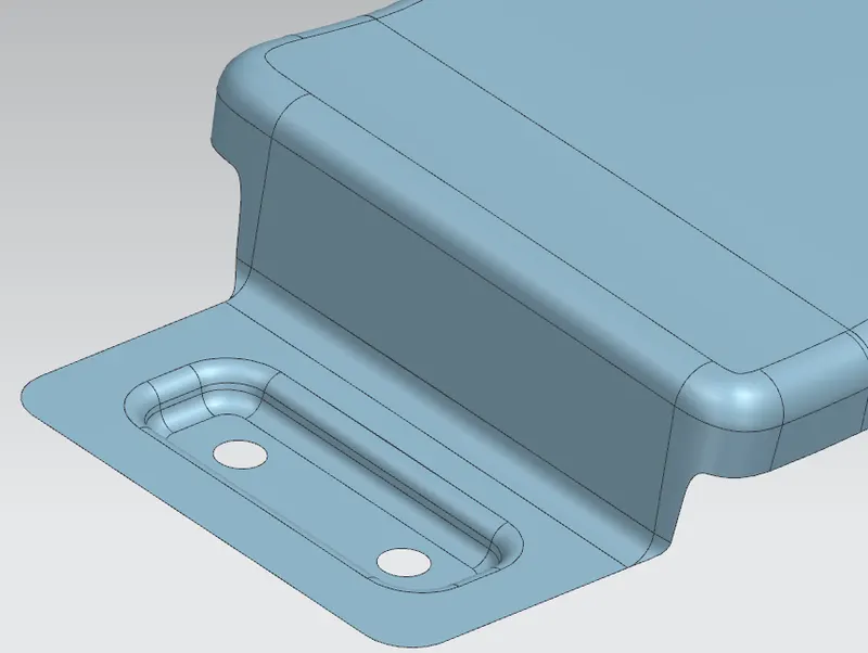
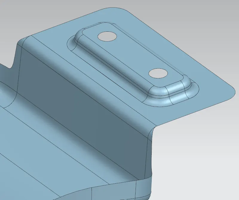
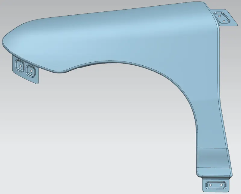
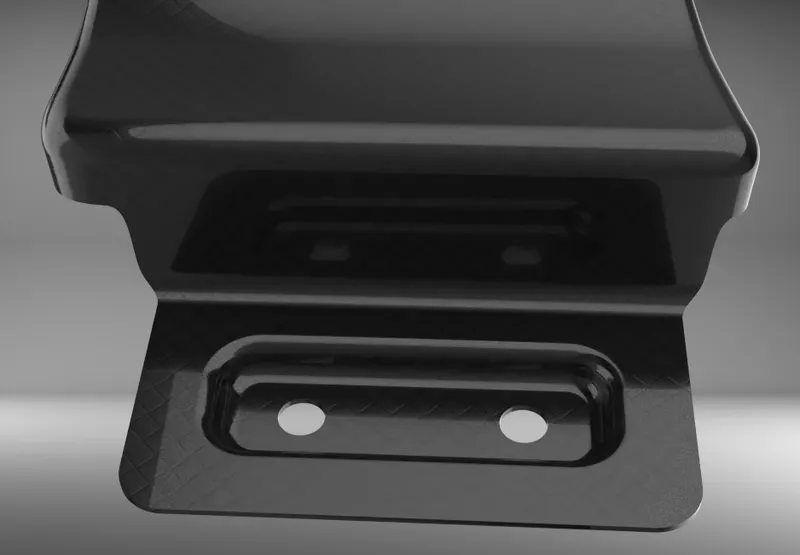
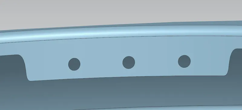
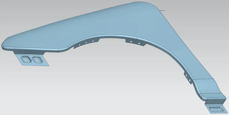
Multiple Baffle Area Mountings: The final aspect of fender mounting surface design involves creating multiple mounts for the baffle area. Within NX CAD software, various techniques, such as utilizing G1 continuity control, may be employed to ensure accurate alignment for baffles that control airflow, turbulence reduction, and acoustic performance. Optimizing these mountings helps achieve improved aerodynamics, reduced noise levels, and overall vehicle performance enhancements.
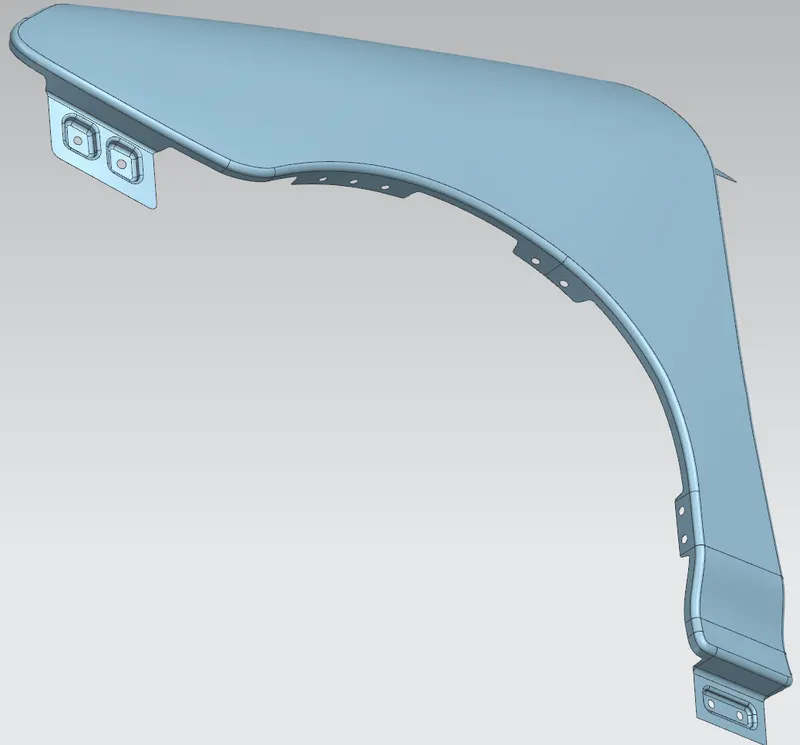
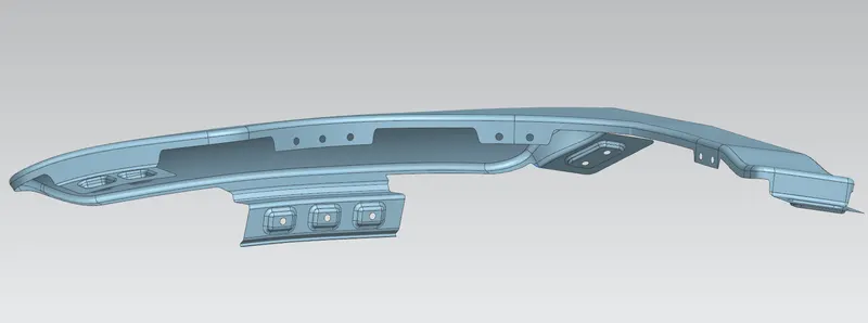
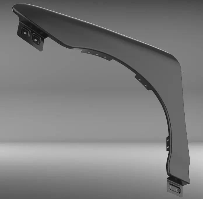
THICKEN OPERATION:
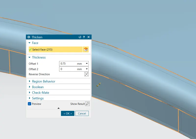
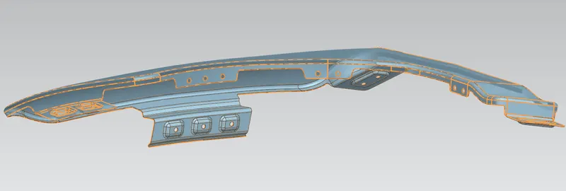
REGIONS AFTER THICKEN OPERATION:
1. BUMPER MOUNT:
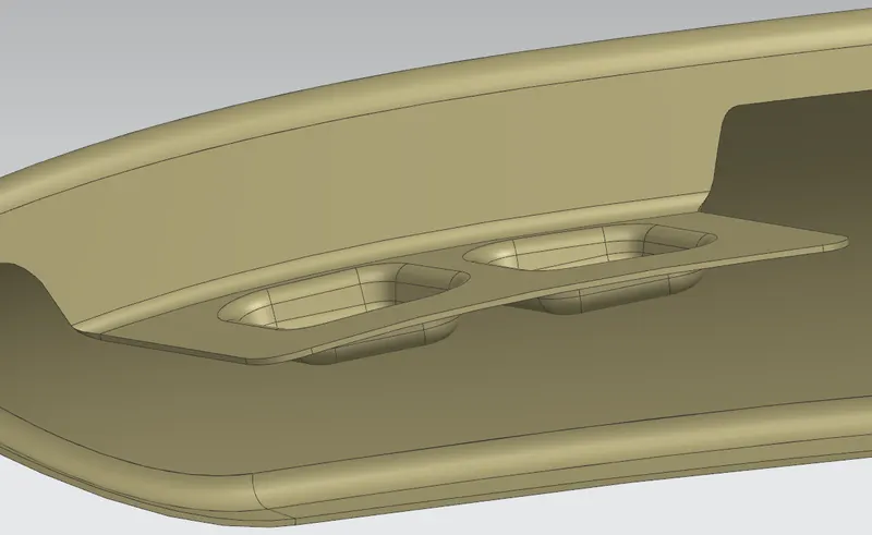
2. SILL MOUNT:
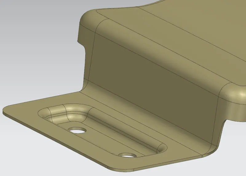
3. A PILLAR MOUNT:
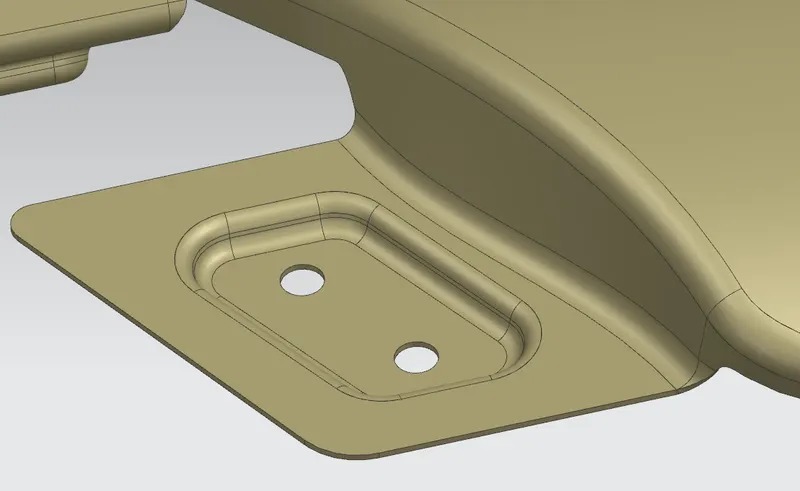
4. DRIP AREA MOUNT:
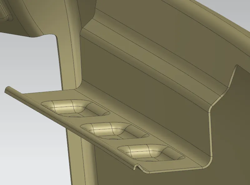
5. MULTIPLE BAFFLE'S MOUNT:
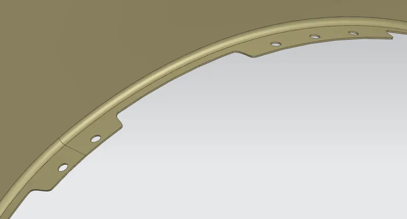
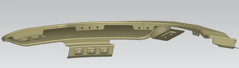
FINAL PART:
CONCLUSION:
In conclusion, the design process for fender mounting surfaces within NX CAD software involves several critical steps that ensure precise connections, functionality, aesthetics, and structural integrity essential to automotive design.