Fender Design
INTRODUCTION :
Front Fender :
It is the covering component. it is one of the closing comomponent for the engine compartment. its primary purpose is to prevent the cars exteriors from the sand, mud, rocks, liquids, and other road debries. all these debries are thrown to exteriors of car by rotating tyre. It is basicaly present to prevent any injuries to pedesterians and also it contains the motion of these particals.
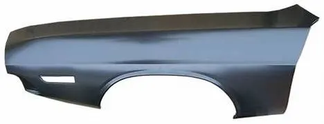
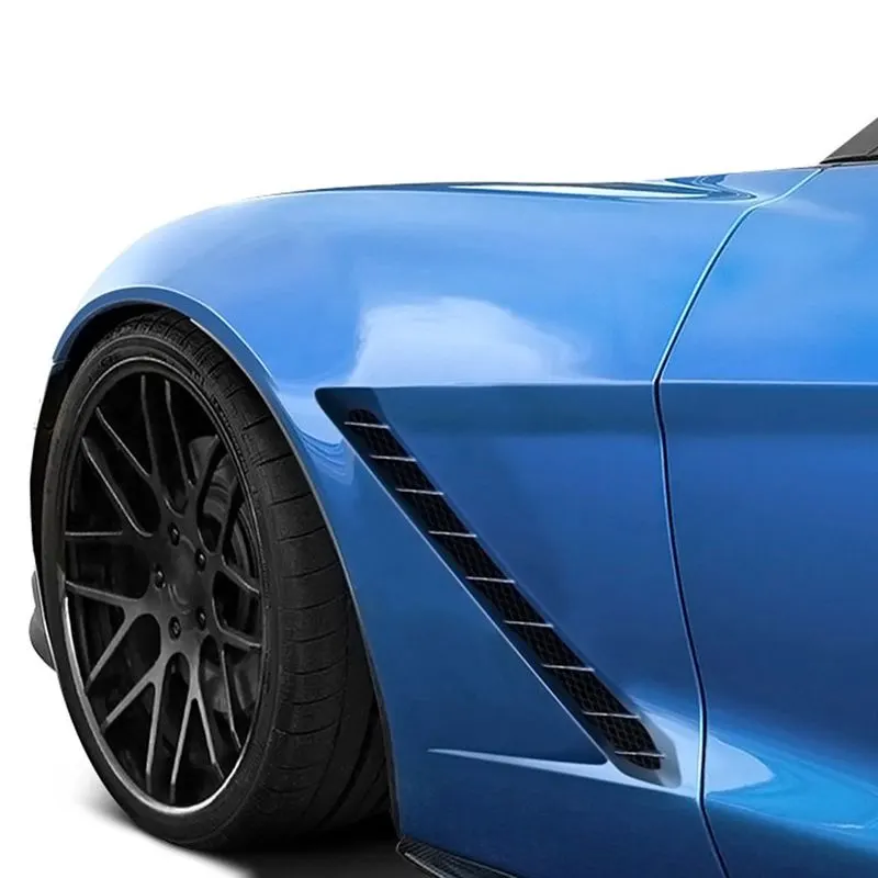
Most pasenger cars have four fenders. one over the each wheel.
there are two types of fenders.
1) full bumper type : in full bumper while manufacturing more srape is produced. hence more blank material requires. and also weight is more.
2) half bumper type : in half buper type while manufacturing less scrape material is produced hence less blank material is required. so less material cost. and also less weight so performance of car gets somewhat improved.
Designing DIFRENT FENDER MOUNTINGS
1) A pillar area mounting
2) sill area mounting
3) COWL area mounting
4) Drip area mounting
5) BODY area mounting
fastners are used to join them. and fastners are closed inside. they are not vissible.
Design considerations
Holes created using the thream sheet with 5mm diameter and the surrounding 5mm area is provided as clearance for the holes so they get sufficient strength. Sharp corners are avoided by giving sufficient relief or edge blends or bridge curve, the sudden sharp corners are avoided. 150mm from cowl area is maintained for drip mounting and all the measurement diementions are followed as per the given mastersection.
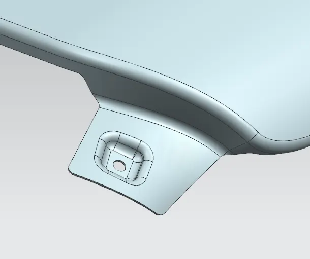
1) A pillar area mounting
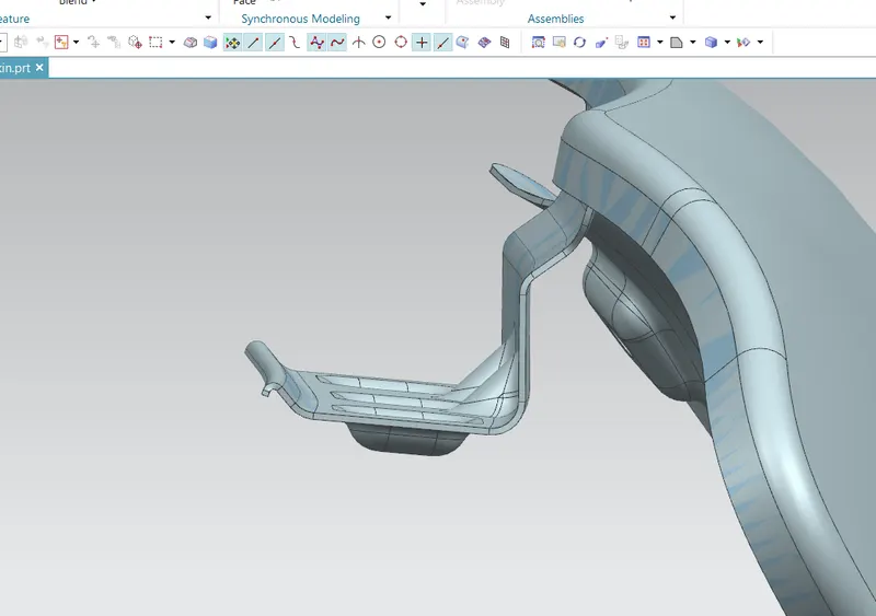
mountings are created on the flat area as shown kin the below photo. also mounting holes are provided with 5mm clearance around the holes. and sharp corners are avoded.
2) sill area mounting
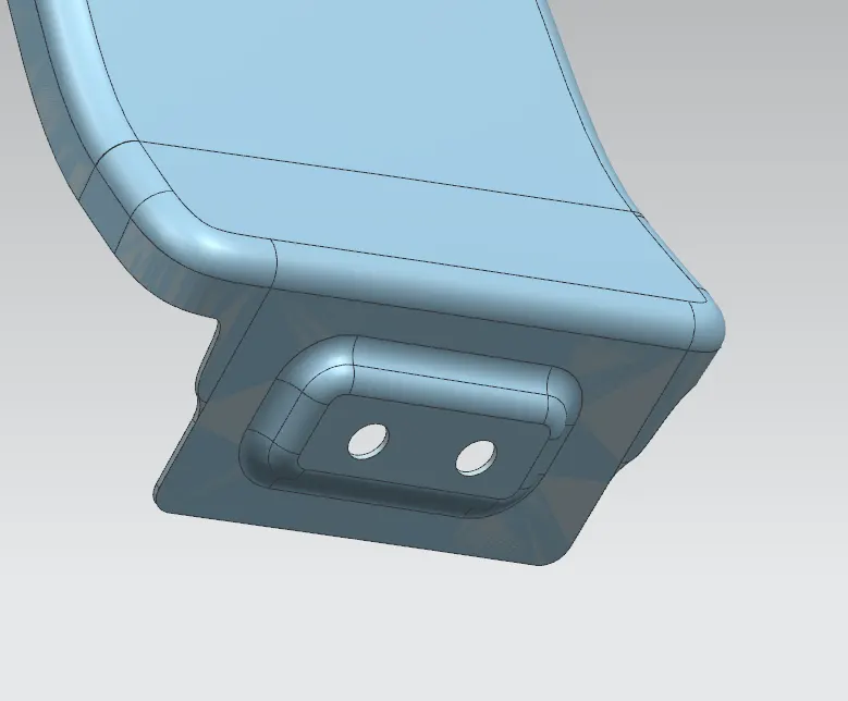
Sharp corners are avoided by providing the edge blend or by creating the relief. Mountings are created on the flat area as shown kin the below photo. also mounting holes are provided with 5mm clearance around the holes.
3) cowl area mounting
cowl mounting also provide with darts and the mountings are created on the flat area as shown kin the below photo. also mounting holes are provided with 5mm clearance around the holes.
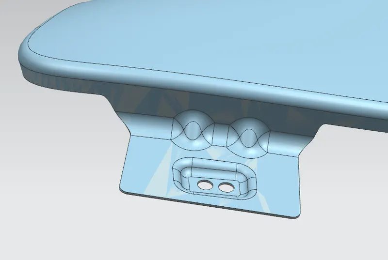
4) Drip area mounting
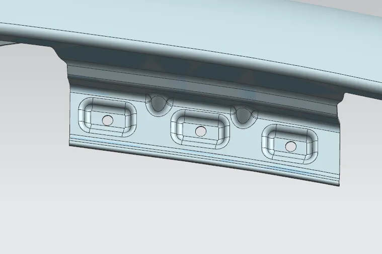
all the diementions are maintained as per the master section given in the question. the drip area mounting is provided 150mm clearance from the cowl or a piller area. and the darts are proveded at corners so the drip area should have the more strength. dart are provided beacuse the drip are get more strength and they donit vibrate more while movement. mountings are created on the flat area as shown kin the below photo. also mounting holes are provided with 5mm clearance around the holes.
5) BODY area mounting
Here, Body area mounting is not created. Because the dore area is jojned using the hinges so the body mounting not required
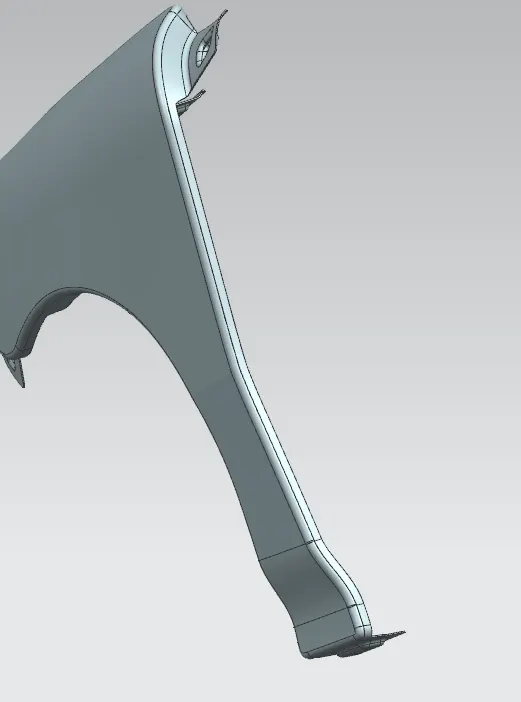
The file of the fender part is attached as part, stp and the zip file folder.