Fender Design
*FENDER DESIGN CHALLANGE :-
1) OBJECTIVE :-
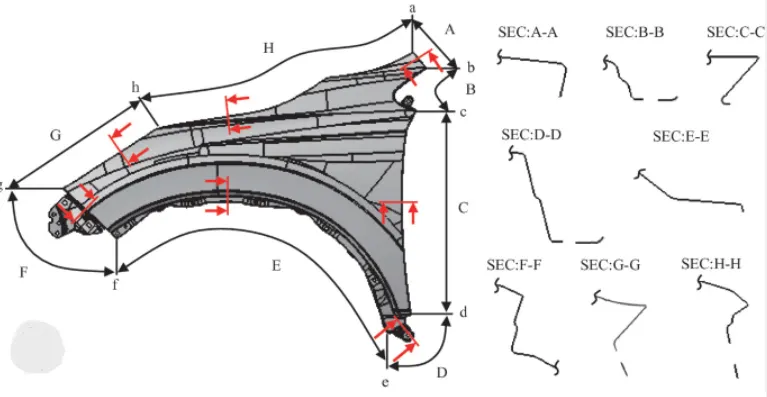
THE OBJECTIVE OF THIS PROJECT IS TO DESIGN CAR FENDER USING CAD MODELING SOFTWARE SIEMENS NX-CAD CONSIDERING ALL THE DESIGNS RULES AND THE MASTER-SECTION PROVIDED.
2) INTRODUCTION :-
Design of any product starts from an requirement . The design engineer sketches the product based on the the requirement . Then the 2D sketch with the proper dimensions is converted into the 3D model using the advanced CAD software's . The another important thing in the design is that , every product that is designed should be able to manufactured . so the role of the design engineer is to design the product that can be easily manufactured and with less cost effective . This is the place where the Design for manufacturing [DFM] and Design of assembly [DFA] takes a role while developing any product . The process of development of design carries on until the design satisfies the customer needs .Here in this project the product that we are going to develop is a car fender.
A) FENDER :-
Who does not want to have an attractive-looking or appealing vehicle? Exquisitely designed structural components like bumpers and fenders make vehicles look stunning. A car fender is a structural component of the vehicle’s body that protects and frames its wheels. Its primary purpose is to prevent sand, mud, rocks, liquids, and other roads spray from being thrown into the air by the rotating tire. This high-speed debris that flies off from the road can hurt the driver and pedestrians as well as damage the parts of the vehicle. Hence, they can be called “defenders of road debris”.
B) HISTORICAL ASPECTS - HOW FENDER EVOLVE AS MAJOR ELEMENT :-
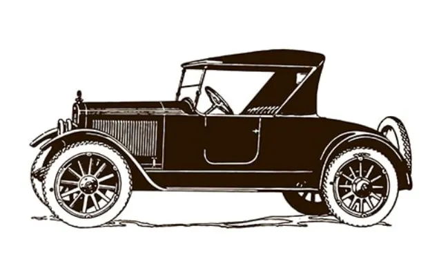
By the early 1900s, American and European-made motorcars had rudimentary fenders over the wheels to keep the driver and passenger safe from mud and sludge. It is believed that the first automobile fender was invented in 1901 by Frederick Simms, although Carl Benz had already mounted a cycle fender in 1894 on his patent motor wagon. Initially, car fenders were used to prevent the splash of roadways into the passenger compartment of open cars. By 1910, more wide and long fenders with running board combinations became prominent. Body stylists regarded them as a necessary feature, but one relegated to a single job, keeping the dust particles and mud under control.

In the 1920s, it was believed that Harley Earl gave the concept that if we extended the front fender rearward and added a recess at the bottom, you could mount the spare tire there. Then in 1933 skirted fenders were introduced in the American automobile industry. Earl redesigned the skirted fender and introduced a pontoon fender look that made the fender an even more prominent styling element.
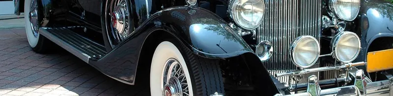
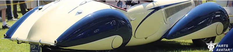
The most influential stylists of the 1940s, at least as far as fender lines are concerned, were Jacques Saoutchik and Joseph Figoni. Figoni Cabriolet is the pioneer in defining the modern fender. While designing these fenders, Figoni also implemented aerodynamic shapes, which help reduce drag and increase its speed. Modern fenders are designed in such a way that, along with performing the above function, they also improve the aesthetics of the vehicle. Figoni Delahaye has one of the most spectacularly designed fenders, which left everyone speechless.
C) HOW MODERN FENDER ARE DIFFERENT FROM OLD ONES :-
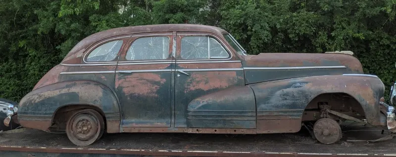
Fenders nowadays came in a more integrated form compared to old vehicles, as the old vehicle’s fenders had a pronounced appearance. Old vehicles, especially from the 1950s, had a unique flair and style, with most of them featuring bubble fenders that stuck out prominently. Modern fenders have evolved a lot with time in comparison to old ones because they not only serve an aesthetic purpose but play an important role in enhancing the aerodynamics of the vehicle. Furthermore, modern fenders are engineered to absorb impact from minor collisions as well. They have a fender liner attached to them that protects the engine bay and other components from potential damage that can be caused by rocks and flying debris. Fenders today also have additional features like grooves and grillwork that are designed to improve the car's performance and can be usually seen in high-end performance vehicles. Another attribute of the modern fender is turn signal lights. By law, all modern vehicles are required to have turn signal lights mounted on the fender.

D) HOW FENDER MATERIALS HAS EVOLVED :-
Of all the features and body parts outside your vehicle, fenders play a key role in protecting your car and other people on the road by housing the wheels. By considering the history and evolution of materials used in the manufacturing of fenders, you can get a complete sense of just how important they are for your vehicle.
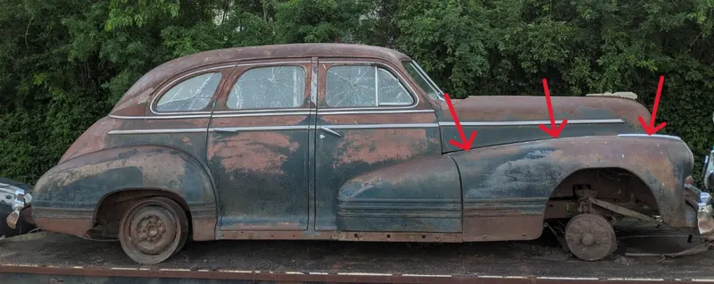
A fender today is a quintessential feature of the car, but back in the old days, they were entirely decorative and made from heavier metals like steel and even wood. Most of the older vehicles used to have a single body part running from the front to the rear of the vehicle, which acted both as a bumper and a fender. These steel fenders were heavy and prone to corrosion. To avoid corrosion and add new styling to the vehicles, chrome was also introduced into their designs. With passing years, the fender design and choice of materials changed. Breaking the traditional use of a single steel component, body parts were manufactured in portions and then assembled together. The most significant innovation during this era was the introduction of plastic fenders and bumpers. With the introduction of plastic, the long reliance on chrome and other metals decreased. This laid the foundation for the improvement of both efficiency and safety of modern vehicles.
E) HOW DOES FENDER OFFERS PROTECTION :-
With time, the safety regulations by the government evolved and so did the aesthetic expectations of the customers. To meet these challenging requirements, automakers started using plastic and steel fenders both and often with bits of chrome. Modern vehicles today are equipped with fenders made from plastic, steel, aluminum, and modern plastic composites like thermoplastic and fiberglass. Usually, heavy vehicles like trucks, utility vehicles, and SUVs are equipped with metal or steel fenders, whereas passenger vehicles have plastic fenders. Fiberglass and thermoplastic fenders can be replaced easily and are inexpensive compared to steel ones. Some high-end vehicles use carbon fiber fenders that are very light and stronger than steel. The use of these composites and advanced materials is aimed at reducing the weight of the vehicle and matching the cost constraints while manufacturing vehicles.
Without a fender housing each wheel well, driving would be very messy. When you drive, your vehicle's tires spin very fast. As they spin, they pick up debris and moisture from the ground and then spray it into the air. The kinetic energy from the tire ejects these materials into the air at high velocity. When that happens, the debris and moisture can:
- Get the vehicle dirty
- Scratch the vehicle
- Get other pedestrians or vehicles dirty
- Hurt other pedestrians
- Damage other vehicles
That's why fenders exist. Fenders catch the debris and moisture before they can hit anything else. In other words, fenders "contain" the dirt and moisture within the wheel well.
F) WHAT PARTS DOES FENDER ASSEMBLY HAVE :-
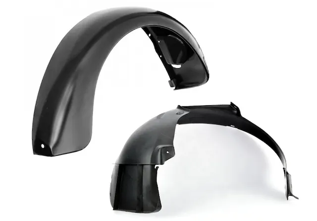
- THE FENDER
- A FENDER LINER
- HARDWARE
THE FENDER ASSEMBLY HAS SEVERAL PIECES OF HARDWARE , SUCH AS :-
- FENDER LINER GORMMET
- FENDER LINER U NUT
G) TYPES OF FENDER :-
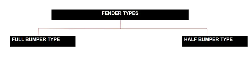
THERE ARE TWO TYPES OF FENDER :-
1) FULL BUMPER TYPE
2) HALF BUMPER TYPE
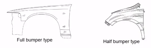

- Presently we are using the half bumper type , the reason for choosing the half bumper type is that when we choose the full bumper type the blank used for creating it is very large and also has the lot of wastage , but in the case of the half bumper type we have the possibility to reduce the scrap . This is what we called as scrap management
- In half bumper type we reduce the usage of the steel material and uses the lots of plastic on the bumper which in term decreases the cars weight and increases the performance
H) MANUFACTURING PROCESS FOR CAR FENDER :-
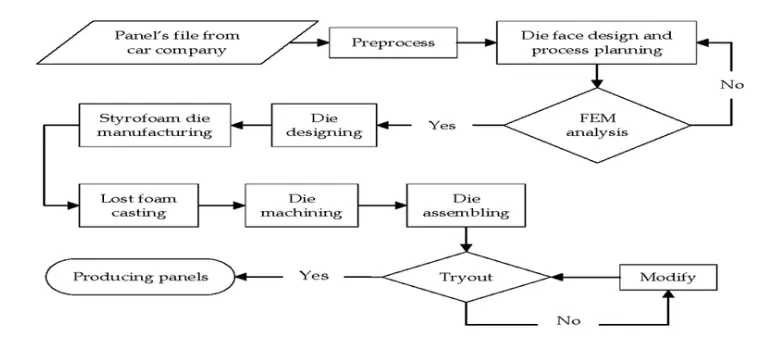
The invention discloses a manufacturing process for a car fender. The manufacturing process includes the following steps that firstly, unfolding and shearing are carried out on a plate, wherein a proper cold roll specification is selected at first, a cold roll is unfolded, and then the unfolded cold roll is sheared to an iron plate of the corresponding size according to production material specifications; secondly, oil pressing and punching are carried out, wherein the iron plate is extended at first, then side shearing and punching are conducted on the iron plate, folding and shaping are carried out on the iron plate, and finally reshaping is carried out on the iron plate; thirdly, small first parts of the fender are machined, wherein first of all, the iron plate is punched to a needed outer contour blank, then the iron plate completing the outer contour blank is further shaped, and the iron plate is punched at last; fourthly, installation and welding of a metal plate are conducted. The manufacturing process for the car fender is simple and high in production efficiency; a body of the fender and the small parts can be separately machined, so waiting time is shortened; working efficiency of production is improved.
PUNCHING :-
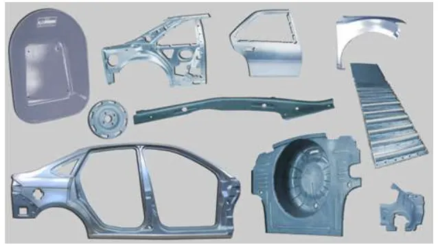
There are several sheet metal punching techniques used in the automotive industry, each with its unique advantages and applications. Some of the most commonly employed techniques include:
- Single-Punching: This technique involves using a single punch and dies to create a hole or cutout in the sheet metal. It is suitable for producing simple, low-cost components with relatively low production volumes.
- Turret Punching: Turret punching utilizes a machine with multiple punches and dies mounted on a rotating turret. This allows for rapid tool changes and the production of complex parts with multiple holes and cutouts. Turret punching is well-suited for the high-volume production of intricate automotive components.
- Progressive Punching: Progressive punching uses a series of punches and dies arranged in a linear or circular pattern on a stamping press. The sheet metal moves through the press, with each station performing a specific operation, such as punching, forming, or bending. This technique is ideal for producing complex, multi-step components with high precision and efficiency.
STAMPING :-
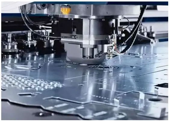
It introduced a stamping process based on three-step of fender, in order to reduce the quantity of dies, and decrease the tooling investment. The product characteristic, stamping formability, and die structure were analyzed. The die quantity of fender was reduced from four-step to three-step by using several compound structures. The side flanging and side piercing, the side restriking and side piercing were arranged in the same step, and the process plan was industrialized application finally. The three-step process was proved to be a feasible plan by practice. So the die quantity was reduced, the stamping efficiency was improved, the die development and production cost were cut down. The quality of three-step process could meet the demand of fender mass production, so there was some reference significance for shorten the stamping process.
BENDING :-
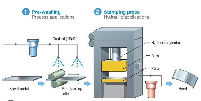
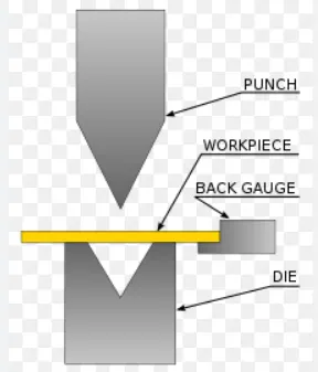
Bending is a manufacturing process that produces a V-shape, U-shape, or channel shape along a straight axis in ductile materials, most commonly sheet metal. Commonly used equipment include box and pan brakes, brake presses, and other specialized machine presses.
DRAWING :-
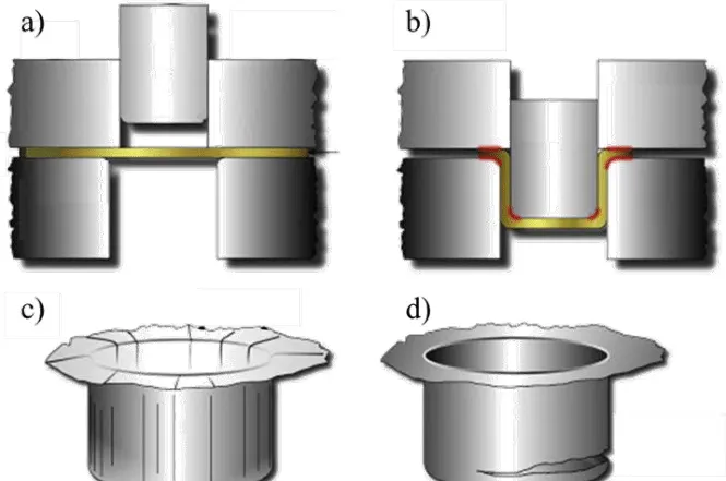
Drawing is a metalworking process that uses tensile forces to elongate metal, glass, or plastic. As the material is drawn (pulled), it stretches and becomes thinner, achieving a desired shape and thickness. Drawing is classified into two types: sheet metal drawing and wire, bar, and tube drawing.
FORGING :-
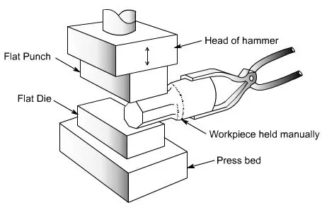
Automotive forging is a manufacturing process, for shaping metal by applying compressive forces with the related equipment. The automotive industry depends significantly on steel forged automotive components owing to increase in vehicle production.
EXTRUSION :-
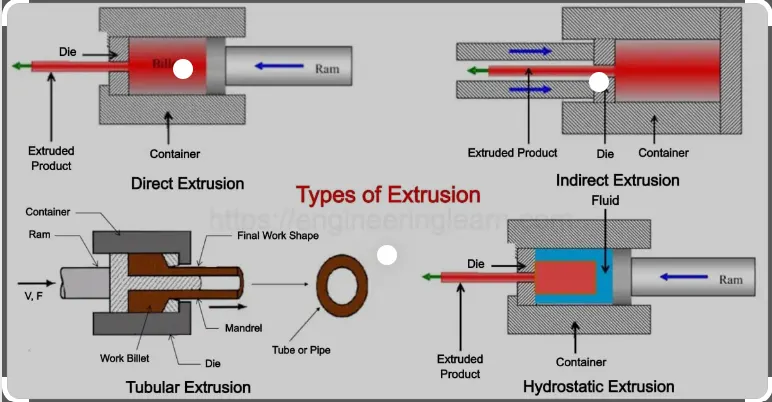
Aluminium extrusion is a manufacturing process that involves shaping and forming aluminium alloys into specific shapes and designs using heat and pressure. The process has found extensive use in the automotive industry due to the various benefits offered by aluminium extrusions over traditional materials like steel.
3) MOUNTING REGIONS ON FENDER :-
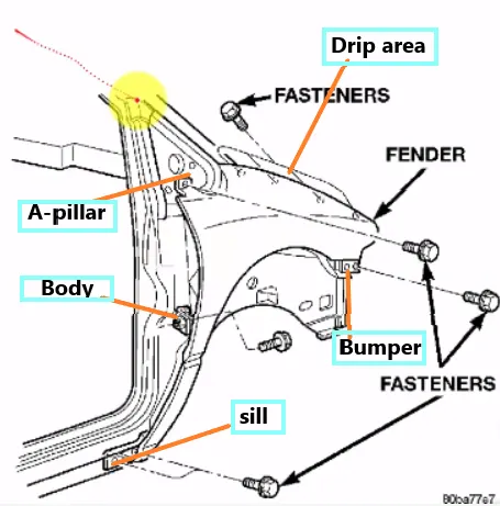
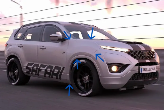
THERE ARE 5 MOUNTING REGIONS IN CAR FENDER, THEY ARE :-
- DRIP MOUNTING
- SILL MOUNTING
- BUMPER MOUNTING
- A-PILLAR MOUNTING
- BAFFLE MOUNTING
4) DESIGN METHODOLOGY, PROCEDURE :-
GIVEN DATA :-
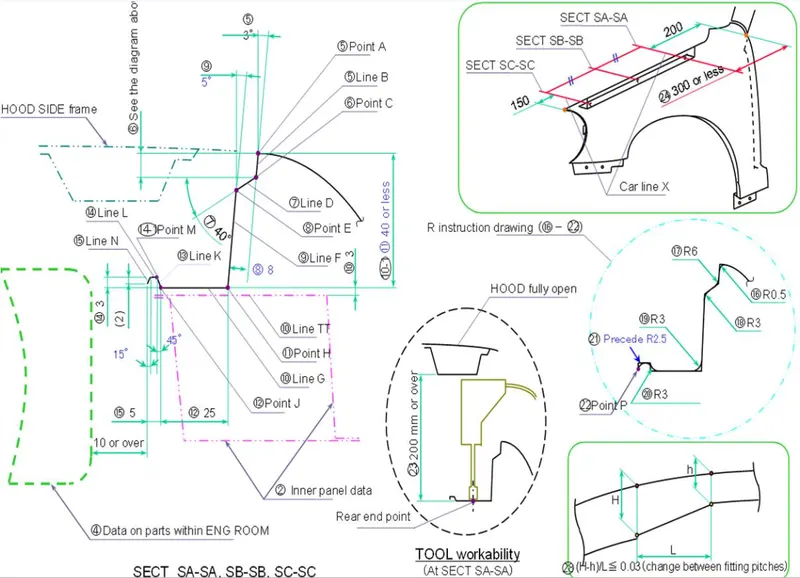
MASTER SECTION
A) DESIGN 0F DRIP AREA MOUNTING :-
- DRIP AREA IS THE IMPORTANT FENDER MOUNTING REGION AS IT CONNECTS THE FENDER TO THE ENGINE COMPARTMENT, THEREFORE A LOT OF DESIGN CONSTRAINTS TO BE FOLLOWED WHILE DESIGNING FENDER DRIP AREA.
- WHILE DESIGNING THE DRIP AREA WE HAVE TO INITALLY LEAVE 200-300mm FOR COWL TOP.
- FOR PLACING HEADLAMPS WE HAVE TO LEAVE ATLEAST 150 mm OF GAP AT THE FRONT WHILE DESIGNING THE FENDER.
- COWL TOP CONSIST OF WIPER MOTER AND ITS INSTRUMENTS.
- TWO DARTS ARE ADDED ON THE LONGER SIDE OF THE DRIP AREA ON ORDER TO PROVIDE STIFFNESS AND STRENTH TO THE COMPONENT . THIS HELPS TO REDUCE SPRING BACK EFFECT WHEN THE VEHICLE IS IN MOTION.
A) TO CREATE DRIP USE LAW EXTENSION COMMAND TO CREATE FLANGE ON DRIP MOUNTING SECTION OF THE FENDER WITH THE HELP OF MASTER SECTION.
B) THEN,CREATE A PLANE USING 3 POINTS AT THE APPROPRIATE POSITION AND THEN CREATE A SKETCH ON PLANE TO GET THE EMBOSS OF APPROPRIATE DEPTH AND ANGLE.
C) THEN CREATE A HOLE USING TRIM SHEET COMMAND OF 5MM RADIUS SURROUNDING 10 MM OF CLEARENCE FOR SCREW FASTENERS TO GET AT ITS PROPER POSITIONS.
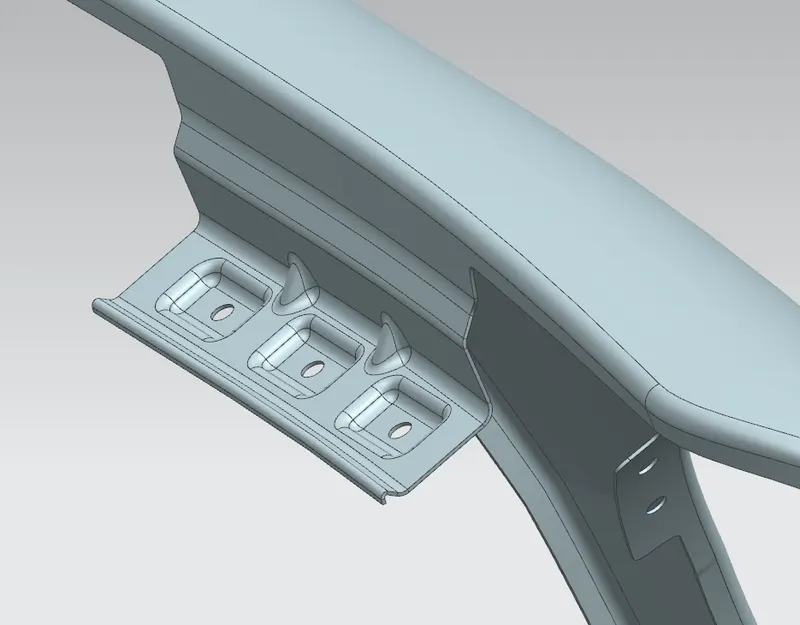
DRIP AREA MOUNTING
B) DESIGN OF SILL MOUNTING AREA :-
SILL IS THE PANEL DIRECTLY BELOW THE BOTTOM OF THE DOOE SUPPORTING THE FLOOR AND MAY BE USED TO COMBINE THE BLOOR AND THE BODY. THE BOTTOM END OF THE FENDER IS MOUNTED ON THE SILL BODY FOR REINFORCEMENT OF THE FENDER PANEL. M5 FASTENERS ARE USED TO FIX THE FENDERS ON THE SILL BODY.
A) TO CREATE SILL MOUNTING USE EXTEND SHEET COMMAND TO CREATE FLANGE ON SILL MOUNTING SECTION OF THE FENDER.
B) THEN,CREATE A PLANE USING 3 POINTS AT THE APPROPRIATE POSITION AND THEN CREATE A SKETCH ON PLANE TO GET THE EMBOSS OF APPROPRIATE DEPTH AND ANGLE.
C) THEN CREATE A HOLE USING TRIM SHEET COMMAND FOR SCREW FASTENERS MOUNTING REGION.
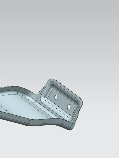
SILL MOUNTING
C) DESIGN OF BUMPER MOUNTING AREA :-
BUMPER MOUNTING AREA IS THE REGION WHERE THE FRONT BUMPER OF THE CAR IS MOUNTED WITH THE HELP OF SCREW FASTENERS TO THE FRONT FENDER OF THE CAR.
A) TO CREATE BUMPER MOUNTING USE LAW EXTENSION COMMAND TO CREATE FLANGE ON BUMPER MOUNTING SECTION OF THE FENDER.
B) THEN,CREATE A PLANE USING 3 POINTS AT THE APPROPRIATE POSITION AND THEN CREATE A SKETCH ON PLANE TO GET THE EMBOSS OF APPROPRIATE DEPTH AND ANGLE.
C) THEN CREATE A HOLE USING TRIM SHEET COMMAND OF 5MM RADIUS SURROUNDING 10 MM OF CLEARENCE FOR SCREW FASTENERS TO GET AT ITS PROPER POSITIONS.
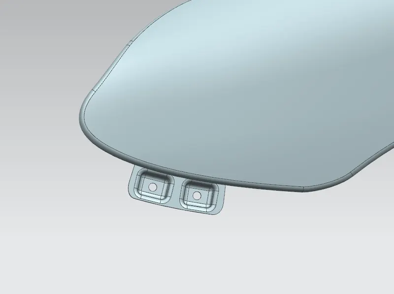
BUMPER MOUNTING
D) DESIGN OF A-PILLAR MOUNTING AREA :-
THE A-PILLAR IS THE STRUCTRAL PILLAR THAT COMBINES THE BODY TO THE ROOF, THIS MAKES THE SIDES OF WINSHIELD REST. FRONT FENDERS ARE FASTENED TO THE A-PILLAR TO FORM ROBUST STRUCTURE.
A) TO CREATE A-PILLAR MOUNTING USE LAW EXTENSION COMMAND TO CREATE FLANGE ON A-PILLAR SECTION OF THE FENDER.
B) THEN,CREATE A PLANE USING 3 POINTS AT THE APPROPRIATE POSITION AND THEN CREATE A SKETCH ON PLANE TO GET THE EMBOSS OF APPROPRIATE DEPTH AND ANGLE.
C) THEN CREATE A HOLE USING TRIM SHEET COMMAND OF 5MM RADIUS SURROUNDING 10 MM OF CLEARENCE FOR SCREW FASTENERS TO GET AT ITS PROPER POSITIONS.
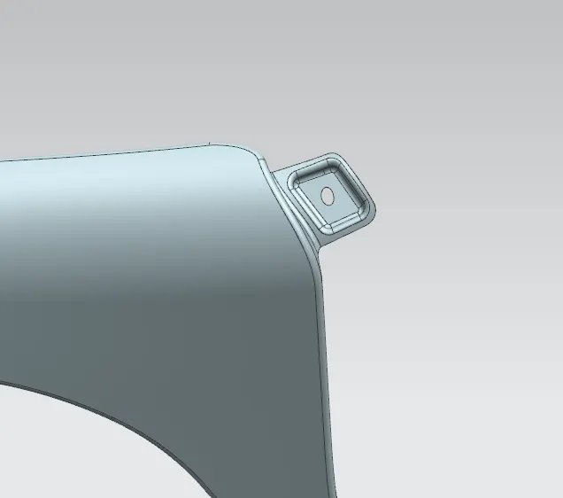
A-PILLAR MOUNTING
E) DESIGN OF BAFFLE MOUNTING AREA :-
BAFFLE MOUNTING OR MUDGAURD ARE THE CLIP FIT TYPE OF MOUNTING ON THE INNER SIDE OF THE CAR FENDER WHEEL ARC OVER THE TYRE. IT PROTECTS THE CAR ENGINE COMPARTMENT AND PEDESTRAINS FROM CAUSING INJURIES FROM CHIP OUT DERBIS ON THE ROAD WHEN THW CAR IS IN MOTION. BAFFLE IS MOUNTED ON THE CAR FENDER WITH THE HELP OF PUSH PIN CLIPS WHICH IS MADE OF PLASTIC.
TO CREATE THE BAFFLE MOUNTING CREATE A PLANE USING 3 POINTS AT THE APPROPRIATE POSITION AND THEN CREATE A SKETCH ON PLANE AND CREATE A CIRCLE IN A SKETCH OF 5MM RADIUS SURROUNDING 10 MM OF CLEARENCE FOR PUSH PIN TO GET AT ITS PROPER POSITIONS.
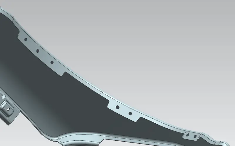
BAFFLE MOUNTING AREA
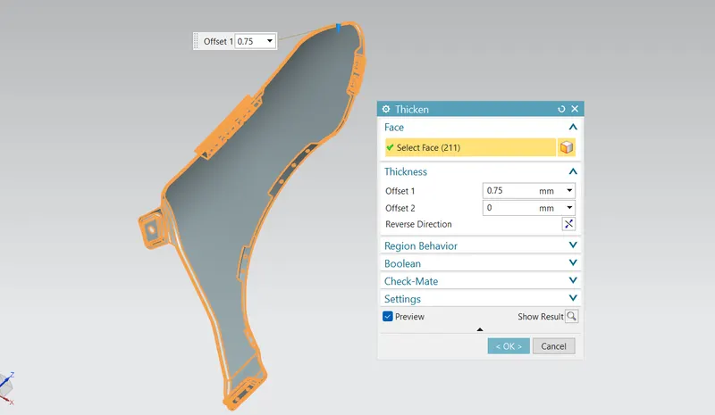
APPLYING OF THICKNESS TO THE SURFACE .
APPLYING THICKNESS OF 0.75 INWARD TO THE FINAL CAR FENDER SURFACE TO CREATE IT AS A SOLID SHEET METAL COMPONENT.
5) IMAGES OF CAR FENDER PART MODEL IN VARIOUS ORIENTATIONS :-
A) FRONT VIEW :- B) TOP VIEW :-
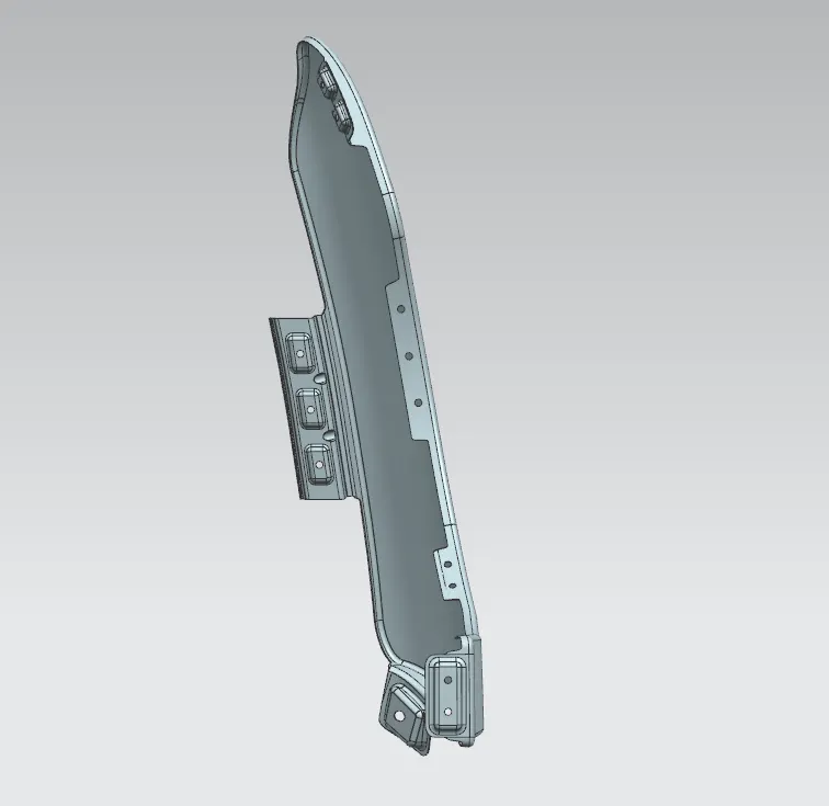
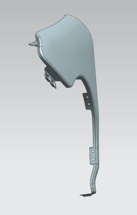
C) ISOMETRIC VIEW :- D) SIDE VIEW :-
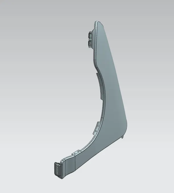
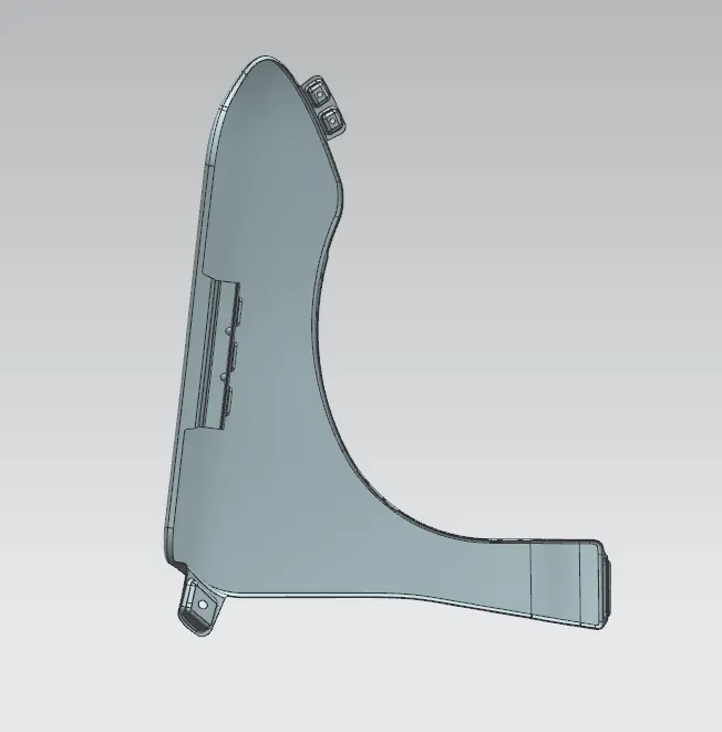
6) CONCLUSION :-
FINALLY I HAD GAINED THE KNOWLEDGE ON HOW TO DESIGN CAR FENDER USING PROVIDED MASTER-SECTION AND DESIGN CONSIDERATIONS ON SIEMENS NX CAD SOFTWARE.