Fender Design
FENDER DESIGN
AIM: To design a front fender of a car by following the given master section as per the design considerations of OEM.
FENDER
It is an aesthetic component/part of a car that frames the wheels. Prevention of sand, mud particles, and other road contaminants from being thrown into the engine compartment and also to the pedestrians by the rotating tires are the main purpose served by the fenders.
The front fenders are separate components whereas the rear fenders are integrated with the body sides.
What are the fenders on a car:
A fender is the part of a car that protects and frames its wheels and keeps mud from splashing it. Most modern vehicles have fenders on their front wheels. When you get into a minor car accident, you can call it a "fender bender," and it's possible that your fenders did get slightly dented.
MOUNTING REGIONS ON FENDER :
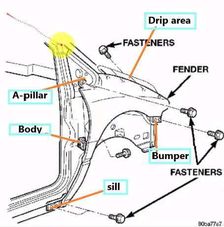
There are 5 mounting regions on the fender , they are
- A- pillar mounting
- Body mounting
- Sill mounting
- Bumper mounting
- Drip mounting
GIVEN DATA :
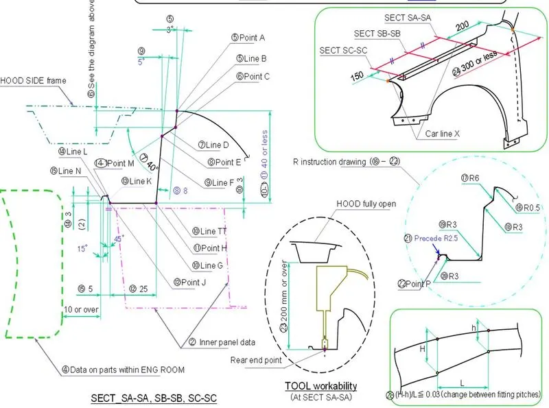
MASTER SECTION
Drip area mounting:
The drip area mounting refers to the specific region where contact occurs between the fender and the engine compartment. When designing the drip area mounting, certain considerations need to be taken into account. Firstly, it should be positioned approximately 150mm away from the front end of the fender to allow sufficient space for placing the headlights. This positioning ensures that the wiring for the headlights is not disturbed by the drip area mounting.
Additionally, the drip area should be located approximately 200mm away from the rear end of the fender. This distance is necessary to maintain adequate space for the cowl top, where the wiper mounting region is installed. By providing enough space in this area, proper functionality and installation of the wiper mechanism can be ensured.
To create the drip area mounting, a master section is provided as a reference. Using the master section as a guide, the sheet material needs to be extended using a law extension technique. The extension should be carried out up to the specified data provided for the drip area mounting.
- Once the drip area is created we going to make a sketch for embosses and hoes for fastners which gives support to that area.
- The darts are also provided in between be embossses which are also used for supporting.
- Make blends at wherever the edges are found.
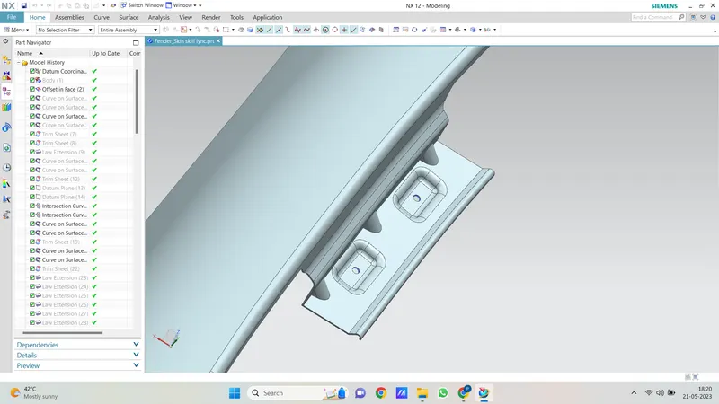
A-Pillar Mounting:
The A-Pillar mounting refers to the area where the fender attaches to the A-pillar part of the vehicle. In the absence of master sections for designing the A-Pillar mounting, assumptions need to be made. However, it is crucial to ensure that sufficient clearance is maintained during the design process, especially when creating embossments or structural features.
To create the A-Pillar mounting, the sheet material needs to be extended using a law extension technique. This extension allows for the necessary material to accommodate the mounting area. Additionally, the curve on surface method can be utilized to create a smooth curve over any sharp edges that may be present. Once the curve is created, the excess material can be removed using a trim sheet technique, ensuring that the final design aligns with the desired specifications.
Overall, the design of the A-Pillar mounting involves assumptions, careful consideration of clearance requirements, extension of the sheet material, and the utilization of curve on surface and trim sheet techniques to achieve the desired result.
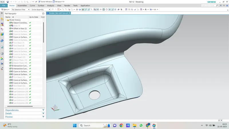
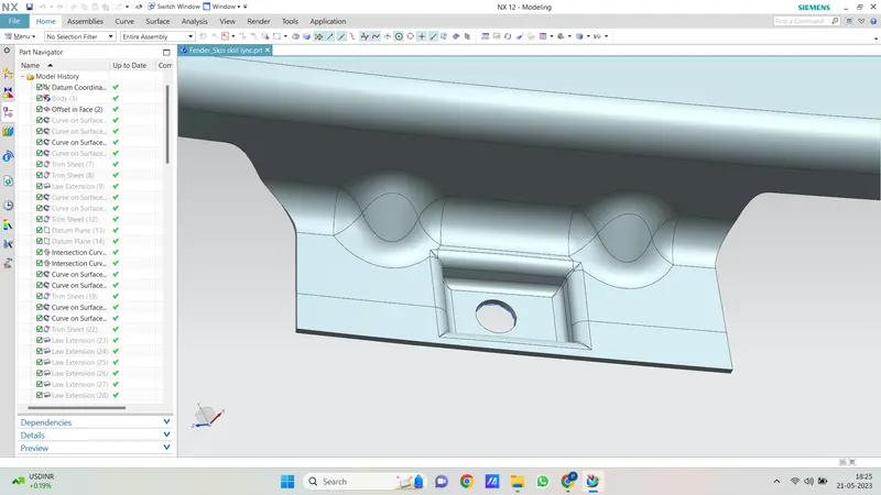
Bumper Mounting:
The bumper mounting refers to the area where the fender attaches to the bumper of the vehicle. To design the bumper mounting, the sheet material needs to be extended using a law extension technique. This extension allows for the necessary material to accommodate the mounting area between the fender and the bumper.
In the design process, a sketch is created to visualize the desired shape and configuration of the bumper mounting. However, if there is limited space available, an open emboss design may be implemented to ensure sufficient clearance and practicality.
To further refine the design, the use of bridge curves can be employed to remove any sharp corners or edges that may exist. By applying bridge curves, the design achieves smoother transitions and eliminates potential stress concentration points.
Overall, the bumper mounting design involves the extension of sheet material, the creation of a sketch or visual representation, the consideration of space limitations, and the utilization of bridge curves to enhance the final design by removing sharp corners.
Sill Mounting:
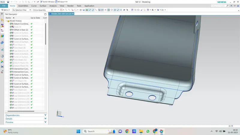
The sill mounting refers to the area where the fender is attached to the sill, which is located below the fender. To design the sill mounting, a sketch needs to be created based on specific considerations and requirements. The sketch will serve as a visual representation of the desired shape and configuration of the mounting area.
Once the sketch is finalized, the emboss command can be utilized to create an emboss in the designated region. The emboss provides the necessary structure and attachment points for securing the fender to the sill. The size and shape of the emboss should align with the design specifications and considerations for the sill mounting.
To ensure a smooth and aesthetically pleasing design, bridge curves can be applied to remove any sharp corners or edges that may be present. The use of bridge curves helps to eliminate stress concentration points and provides a more visually appealing transition between different components.
In summary, the design of the sill mounting involves creating a sketch based on considerations, utilizing the emboss command to generate the necessary structure, and applying bridge curves to refine the design by eliminating sharp corners and edges.
Baffle Mounting:
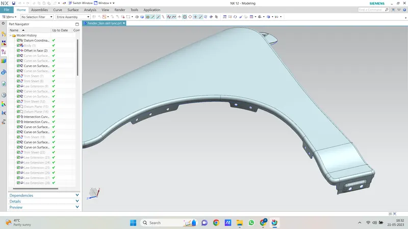
- These mountings are created for attaching plastic components i.e baffle which prevents chips,stones entering inside the fender.It is a thin plastic piece so we no need to create any embosses over there.
- We can directly craete a sketch of holes an then by projecting them onto the object we can trim them.
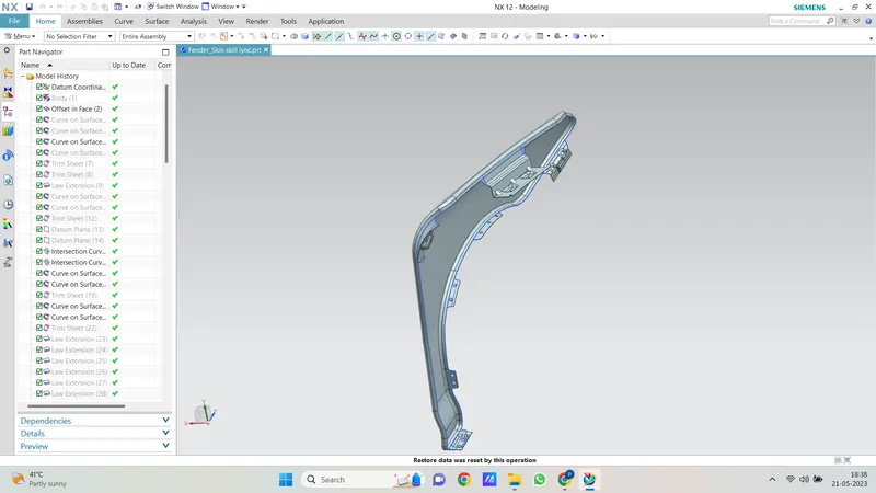
total geometry:
CONCLUSION :
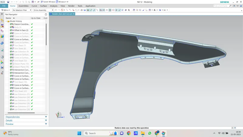
Finally design of fender is done with the help of NX-CAD software by following the master section.