Fender Design
DESIGN OF CAR FENDER
Fender is the part of an automobile, motor cycle or other vehicle body that frames a wheel well (the fender underside). Its primary purpose is to prevent sand, mud, rocks, liquids, and other road spray from being thrown into the air by the rotating tire. Fenders are typically rigid and can be damaged by contact with the road surface.
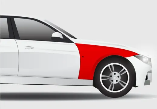
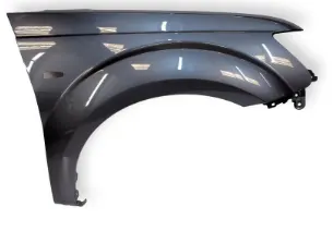
Sticky materials, such as mud, may adhere to the smooth outer tire surface, while smooth loose objects, such as stones, can become temporarily embedded in the tread grooves as the tire rolls over the ground. These materials can be ejected from the surface of the tire at high velocity as the tire imparts kinetic energy to the attached objects. For a vehicle moving forward, the top of the tire is rotating upward and forward, and can throw objects into the air at other vehicles or pedestrians in front of the vehicle.
In ordeer to manitain the pedestrains saftey we have to position the tire wheel inside the fender.
For European requirement he clearence between the wheel and the fender outer most skin is mm.
This requiremnt chsnges from country to country based up on the road condition.
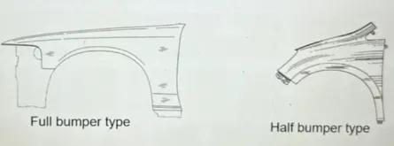
TYPES OF FENDER
- Full Bumper type
- Half Bumper type
AssemblyApproach:
There are two types of assembly, they are
- Bottom_up assembly
- Top_Dwon assembly
Bottom_up Assembly:
The bottom up assembly is the most preferred approach for creating assembly models. In this type oa assembly the components are created in part design work bench (As nx cad part) file. Part are conceived in assembly design workbench using product strcuture tool. After inserting each component, constarints are applied to position them properly in the 3D space with respect to the other components. This assemblies is preffredd for large assemblies, Especially those having intricate indivdal components.
Top_Dwon assembly:
In the top assembly design approach, Components are ceated inside the assembly design work bench. Therefore, there is no need to create sepatre file of the components. This design approach is completely different from the bottom-up design approach. Here you created the product file first and the one by onecreate the product file, they are saved and opended individually one by one when they are needed. Here the construction and the assembly takes places simultaneously.
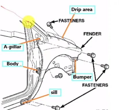
There are 5 ounting regions on the fender, they are
- A-Pillar mounting
- Body Mounting
- Sill Mounting
- Bumper Mounting
- Drip Mounting
Design Parameter:
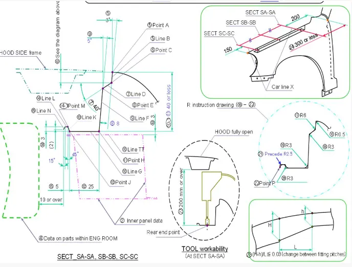
Purpose of Fender :
Cleanliness : Protect the car, occupants and passers by from items, water, mud, snow, ice, thrown off the tires as you drive.
Safety : Protects pedestrain from the wheel, e.g. its better to be it by a laterally moving fender than a rolling tire, keeps loose, streaming items from being wrapped up in a rolling wheel.
Aerodynamics : Smooths the car profile so you don't get a lot of drag off the uncovered wheels. Some fenders are enclosed on the side for this.
General Appearance : Looks better with fender, gives a finished look, looks more streamlined.
DESIGN OF DRIP AREA MOUNTING :
- It is the important mounting unit of the fender . it is connected with the engine compartment , therefore the lot of design constraints are to be followed while designing the fender
- While designing the drip area we have to initially leave 200-300 mm for cowl top
- For placing the headlamp we have to leave at least 150 mm at the front while designing the fender
- Cowl top part consists pf wiper motor and its instruments
- Two darts are added on the longer side of the drip area in order to provide the stiffness and adds strength to the part . This helps the fender to not to vibrate and impact the forces outside of the fender during motion of the vehicle.
- Embossing are provided on the mounting to strengthen them during fastening.
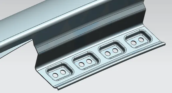
DESIGN OF A-PILLAR MOUNTING AREA :
The A -pillar is the structural pillar that combines the body to the roof . this make the sides of the windshield rest . front fenders are fastened to the A -pillar to form a robust structure.
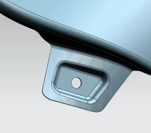
DESIGN OF BUMPER MOUNTING AREA :
Bumper mounting area is used to fix the plastic bumper to the fender with the help of the fasteners.
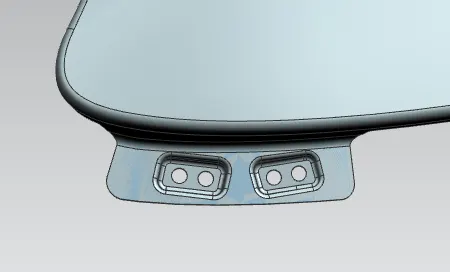
DESIGN OF BAFFLE MOUNTING AREA :
Baffle mounting or mudguard are clip fit type of mounting on the inner side of the fender arch over the Tyre. it protects the car engine compartment and pedestrians from causing injuries from chip out debris on the road when the car is in motion . they are mounted on the fender using a special type of locking clips which are made up of plastics .
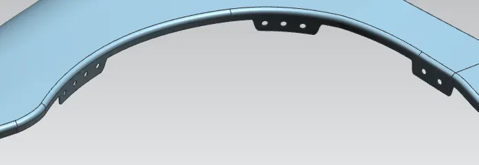
DESIGN OF SILL MOUNTING AREA :
Sill is the panel directly below the bottom of the door supporting the floor and may be used to combine the floor and the body . The bottom end of the fender is mounted on the sill body for reinforcement of the fender panel , thus the sill mounting position is designed with holes and emboss . M5 fasteners are used to fix the fenders on the sill body.
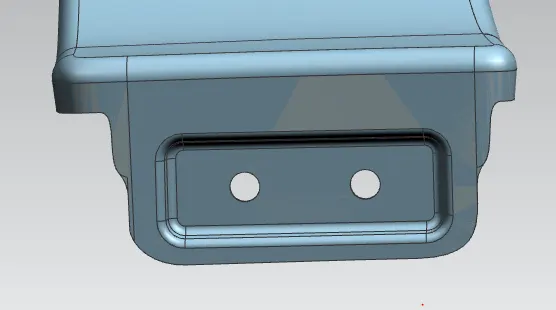
DESIGN OF INDICATOR HOLDER AREA :

APPLYING OF THICKNESS TO THE SURFACE .
The thickness of 0.75 mm inward on the final sewed surface of the fender to the sheet metal parameters.
Commands used from NX CAD to model this fender are:
- Offset in face
- Curve on surface
- Trim sheet
- Law extension
- Datum plane
- Intersection curves
- Face blend
- Bridge curve
- Sketch
- Projected curve
- Emboss
- Edge blend
- Thicken
Conclusion:
The fender of the automobile is checked for the wheel arch radius as per Europen regulations and designed the front half fender of a car using master section and by following the pedestrian's safety and in order to guard the engine compartment and beside the vehicle.