Fender Design
FENDER DESIGN
FENDER
It protects the vehicle from road debris being thrown by tyre as we drive it. They pick-up things like loose rock, mud and dirt along the roadway. At high speed loose rocks can do a severe damage to the vehicle because of its kinetic energy. They also help in holding the bumper and baffle. Fender is generally made aerodynamic in shape to reduce the air drag.
- This fender has been designed in the CATIA-V5 environment and its thickness is 0.75mm.
FENDER TYPES
They are of two types
- Full Bumper types
- Half Bumper types
Full Bumper types:
- This type of bumper was used on earlier models of vehicles and currently they are not manufactured. It will cover the area from the side door to the car's headlight.
- They do more wastage of sheet metal and reduce the vehicle performance by increasing its weight unnecessarily.
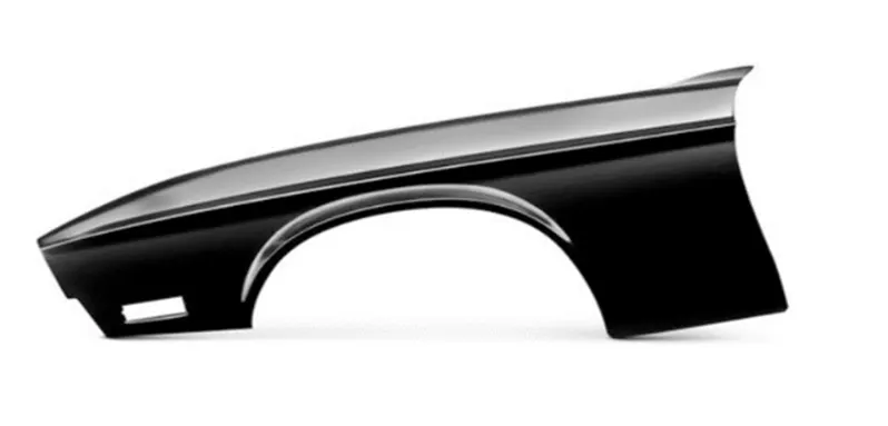
Fig.1
Half Bumper types:
- This type of bumper is used in modern day because of the reduced raw material wastage, reduction in car weight to improve performance and manufacturing cost is low compared to full bumper type.
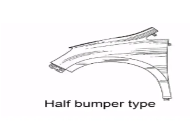
Fig.2
Manufacturing processes used for fender
The manufacturing of the fender majorly involves the following operations
- Embossing
- Bending
- Cutting
- Blanking
Embossing
Embossing is a metal forming process for producing bulging out or inside the surface designs theoretically with no change in metal thickness, or by passing sheet or a strip of metal between rolls of the desired pattern.
Bending
Bending is a process by which metal can be deformed when applying force to the subject, which causes it to bend at an angle and form the anticipated shape, which often results it being in a ‘V’ or a ‘U’ shape. This is done through the application of force using a punch on a workpiece. The force on the work piece can be mechanical, pneumatic or hydraulic.
Cutting
Cutting processes are those in which a piece of sheet metal is separated by applying a shear force that causes the material to cut.
Blanking
Blanking is a steel manufacturing process in which a flat, geometric shape is created by feeding a coil of sheet metal into a press and die. In this process, the blank is punched out from the large metal sheet.
Fender usually consists of 5 following mounting regions
- Drip Area
- A-Pillar Mounting Area
- Sill Mounting Area
- Bumper Mounting Area
- Baffle Mounting Area
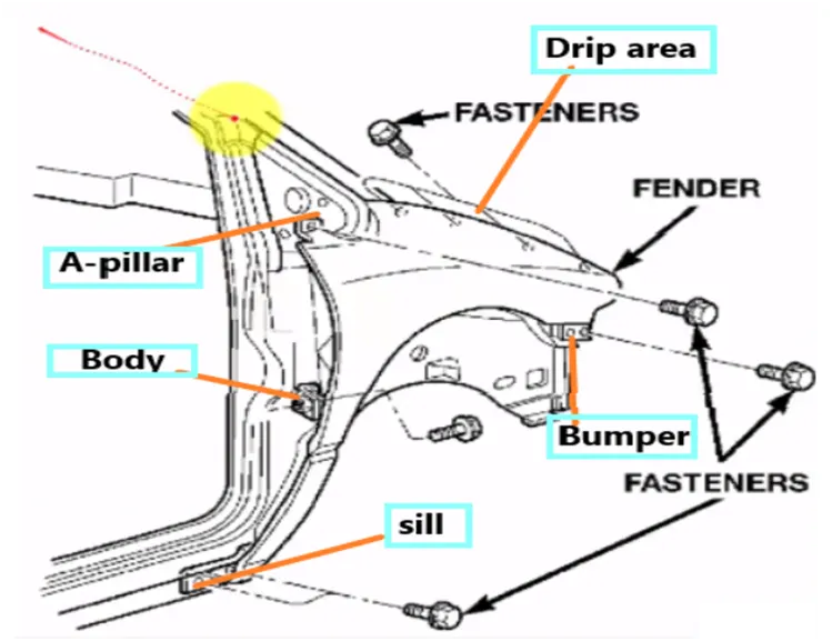
Fig.3
Drip Area
This area of fender is attached to the engine housing by using fasteners. Mountings at the drip area are designed leaving a clearance of 200mm from the back of the fender for the cowl setup and a clearance of 150mm from the front of the fender for a headlamp housing unit. This drip area must not be directly visible to the customer from outside.
DESIGN CONSIDERATIONS OF DRIP AREA MOUNTING:
It is connected with the engine compartment, therefore the following design considerations are to be followed while designing the fender.
- The drip area we have to initially leave 200-300 mm for cowl top
- For placing the headlamp we have to leave at least 150 mm at the front while designing the fender
- Cowl top part consists of wiper motor and its instruments
- Two beads are added on the longer side of the drip area in order to provide the stiffness and provide strength to the part. This also helps the fender not to vibrate by reducing its NVH.
- Emboss with flat surface is provided on the mounting so as to provide it a secure fastening.
MASTER SECTION OF DRIP AREA:
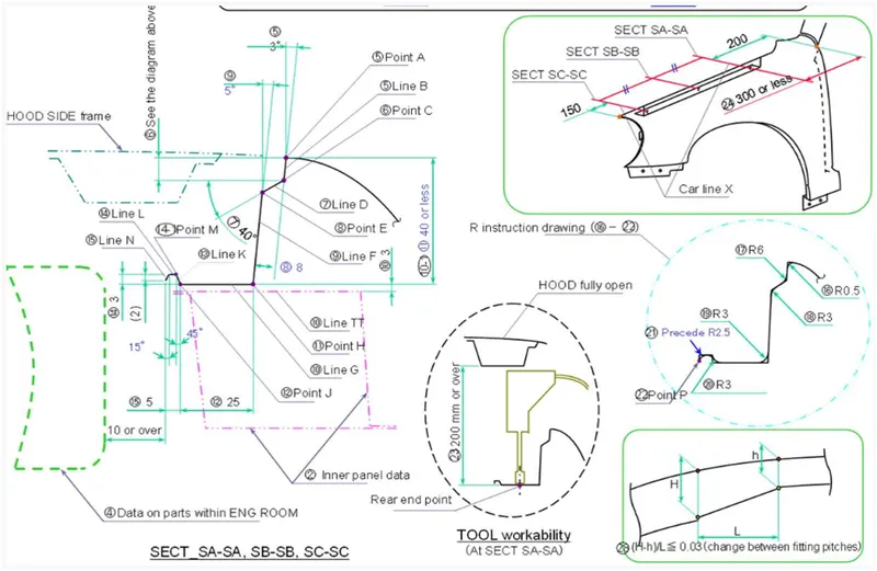
Fig.4
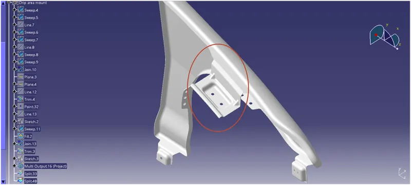
Fig.5
DESIGN CONSIDERATIONS OF SILL MOUNTING AREA:
Sill is the panel directly below the bottom of the door supporting the floor and may be used to combine the floor and the body. The bottom end of the fender is mounted on the sill body for reinforcement of the fender panel, thus the sill mounting position is designed with holes and emboss to secure them.
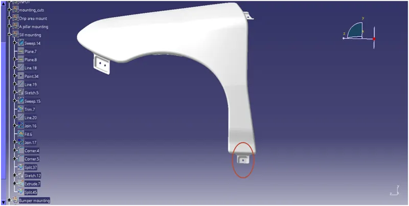
Fig.6
DESIGN CONSIDERATIONS OF BUMPER MOUNTING AREA:
Bumper mounting area is used to fix the plastic bumper to the fender with the help of the fasteners.
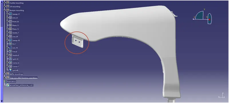
Fig.7
DESIGN CONSIDERATIONS OF A-PILLAR MOUNTING AREA:
The A -pillar is the structural pillar that connects the vehicle body to the roof. This makes the side of the windshield rest. Front fenders are fastened to the A -pillar to form a robust structure.
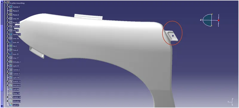
Fig.8
DESIGN CONSIDERATIONS OF BAFFLE MOUNTING AREA:
Baffle mounting lies on the inner side of the fender arch that lies over the Tyre. It protects the car engine compartment from damage and pedestrians from causing injuries because of the debris chipping out on the road when the car is in motion.

Fig.9
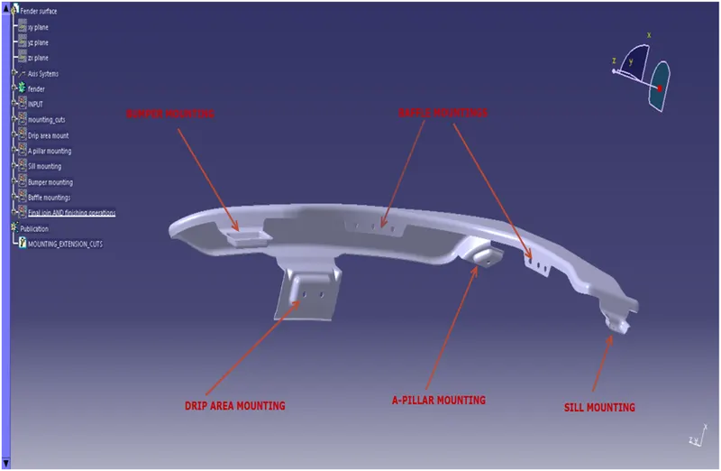
Fig.10 final finished part
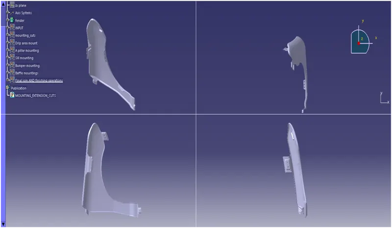
Fig.11 views in different orientations