Fender Design
Aim: To design the Front Fender using NXCAD.
Objective:
Design the Fender with the necessary Mounting areas given below:
- Drip area
- A-Pillar mount
- Sill mount
- Bumper mount
- Baffle and splash mount
About Fender:
Fender is the American English term for the part of an automobile, motorcycle, or other vehicle body that frames a wheel well (the fender underside). Its primary purpose is to prevent sand, mud, rocks, liquids, and other roads spray from being thrown into the air by the rotating tire.
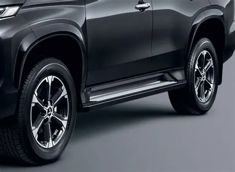
Types of Fenders:
The type of fender is based upon the area covered i.e., full fender type and half fender type.
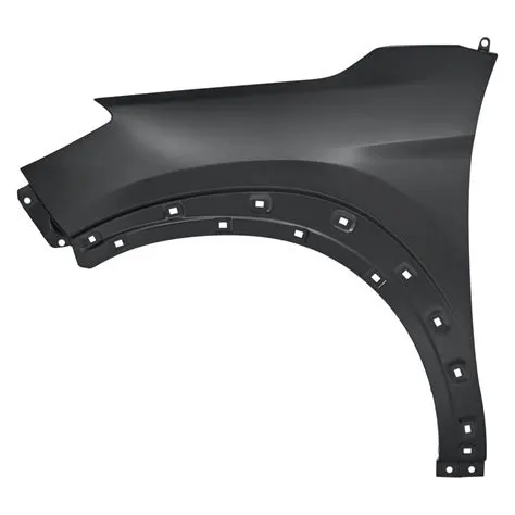
Full Fender Type Half Fender Type
>Full fender type is traditional type of fender where more material consumption is observed. This type is used in old design of automobiles where it increases the overall weight and thus reduces performance. The maintenance also relatively more due to more surface.
>Half fender type is modern design where less material consumption is observed, so productivity increases by reducing size of blank and thus providing more performance. The maintenance also relatively low compared to full bumper type.
Drip mounting:
>A drip area is mounted below the hood to connect it with the fender. It is designed like when the hood is in closed condition this region needs to be flush out and there will be fewer gaps, so the inner area of the engine compartment will not show through the gap.
>The drip area is bolted down by self-tapping screws and sometimes it also spots welded. The given master section shows the criteria as a design parameter for designing the drip mount.
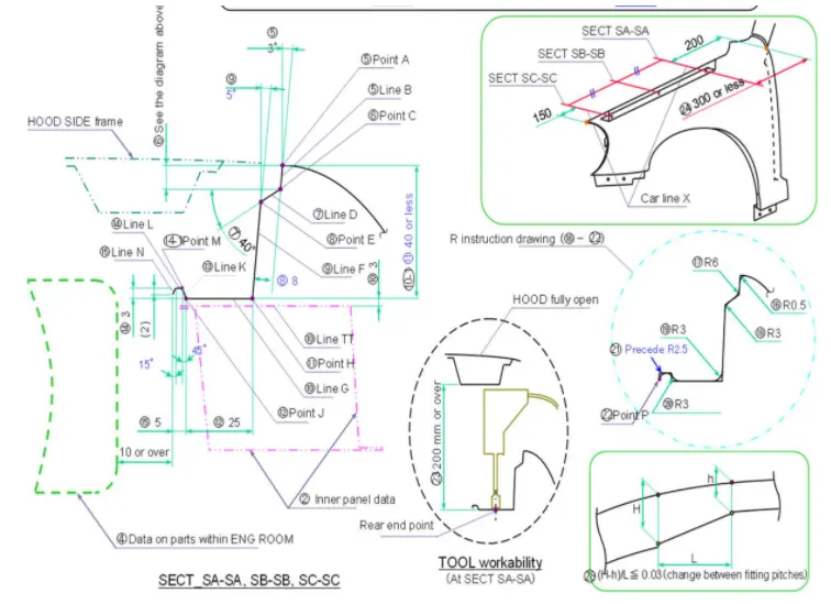
>As per the master sketch we are going to design the drip mount and we will follow the design parameters as per industry for the other mounting area too.
>The drip area is made 150mm away from the front end of the fender which is kept for a headlamp in the bumper & 200mm away from the rear end is kept for wiper motor assembly. And we are going to design the fender in NX CAD.
>So first we are going to work on the drip mount which will mounted to the engine compartment.
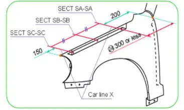
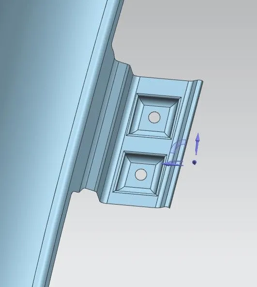
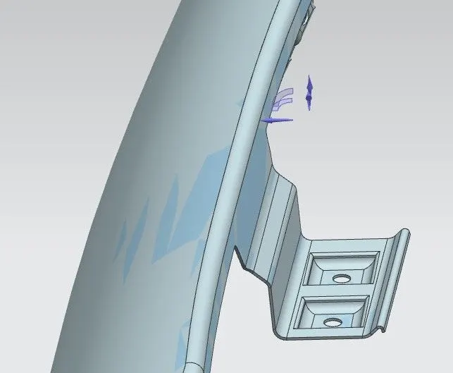
1.Drip mount
>As you can see in the above images we have created some emboss and mounting holes for the fasteners we have created flat surface and have given the minimum 5mm flat area around the mounting holes.
>And we have also provided darts to it to increase the strength of the mount.
2.A-PILLAR Mount:
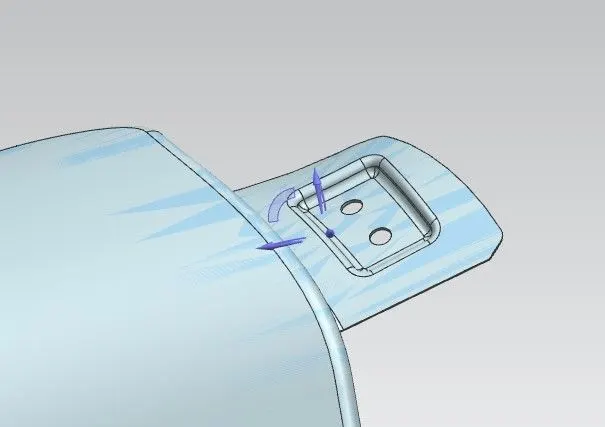
>While creating this mount was tricky one as we have create a emboss on curved surface so for that we have used datum plane and according to that we have created the sketch.
3.Sill mount:
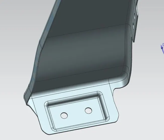
>Like drip mount we have created the sill mount too and we made sure that we didn’t have any sharp corners and we provided relief to it.We did this by using bridge curve and trim sheet.
4.Bumper mount:
>As you can see we have created the bumper mount using emboss, dart and bridge curve to cut out the sharp corners.
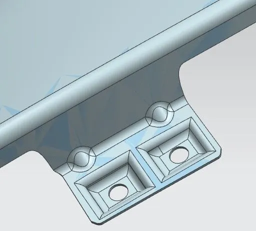
>Here we are provided an dart with the radius of 3mm and depth of 2mm for the region of bumper which sholud be strengthen.
5.Baffle Mount:
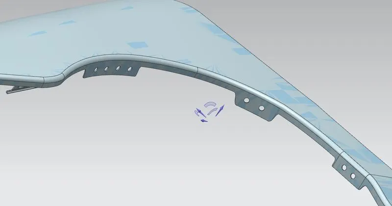
>For baffle mounting we didn’t made any kind of emboss we have created the mounting holes for it and we have created the baffle flange on which the holes are there.
>After creating the mounts we finally thicken it which gives thickness to the sheet metal.
Fender View:
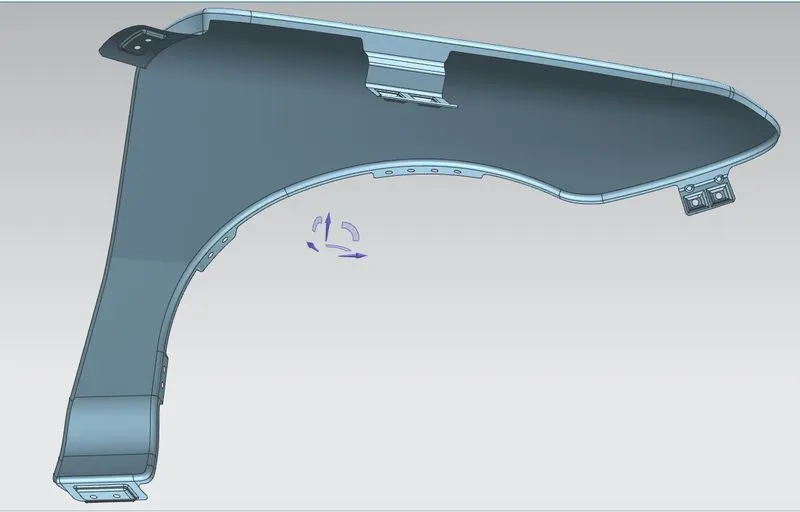
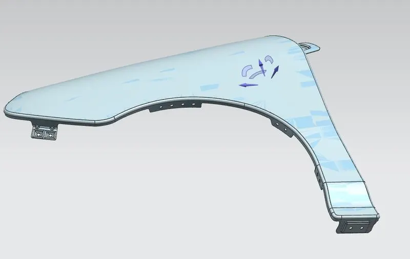
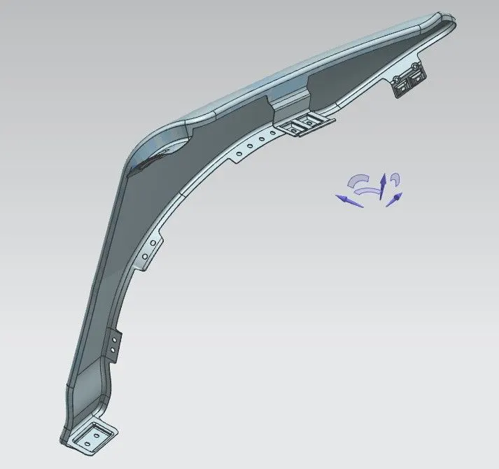
>The above images are shown the full design of fender.