Fender Design
WHAT EXACTLY FENDER IS...?
WHILE Fender is a front outerside member of a car, which covers the wheel side. It has so many small features with ups and downs.
The binder surface is not a planer one in this case. This is because to reduce the draw depth and it has two rows of draw beads. It
seems to be difficult to form due to their small radius fillets. In this analysis, there is a need to find out the forming feasibility of
this component and a if not possible in single stage then we need to modify the die design with least modification and need to
optimize the draw bead profile and draw radius in such a way that we can get the good component in a single stage itself. For thin
and very big forming dies, we need to do gravity analysis. If our die face is profiled one, then we may need to do binder wrap
analysis. The binder wrap analysis results are taken to the forming analysis. After the forming analysis, if trimming is there means
just before trimming analysis we have to do mesh coarsening. Then the coarsened mesh and its results are taken for trimming
analysis. The results of the trimming analysis are taken to the spring back analysis. From the results of the spring back analysis,
further we can cross check the spring back of the real component. The analysis results obtained is used in sheet metal industry for
metal forming process.
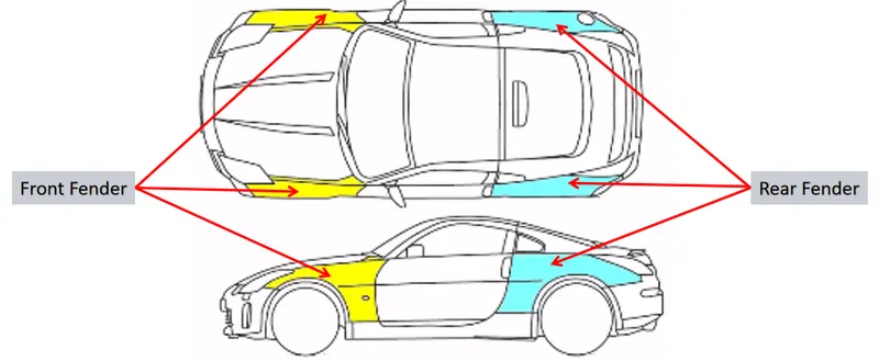
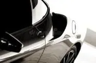
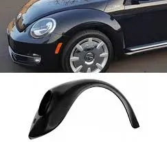
Types of fenders
Fenders are classified into two main types
- Full bumper type
- Half bumper type
Full bumper type:
For full bumper type I have presented some good examples to show how it looks
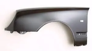
Half bumper type:
Half bumper type are used in new generation vehicles where in the weight of the part is reduced and also the cost. Here the scrap can be saved during material stamping or cutting process by using the half bumper design.
Here are two examples to understand the design.

Also there are Some Different Standards Followed In Different Regions.......
WHAT IS FENDER STANDARDS :-
Fender Standards are Kept On Consideration Of Pedestrian Safety...Because when a car Moves at an Perticular Speed take an Example of 60 km/h then obviously the wheels of car throw some Debris, Mud,Sand,Stones and due to this Pedestrians May meet With an Accidentor any body who is near to Moving car so by taking Consideration Of All Safety some standars should Follow In Design OF Fender .......
WHY DIFFERENT STANDARDS FOLLOWED.....?
European Standars are Different From Japnease Standards...?
Because as Compared to Grographical Size Of Europe the Cars present on Roads of Europe are less so the avg speed of every Car Present on road of Europe (eg 60km/h) so the Debris or Stones thrown By the Wheel of Cars are high so by taking consideration of it they kept it at an 10 mm..On the Otherside as Compared to Grographical Size Of japan the Cars present on Roads of japan are high so the avg speed of every Car Present on road of japan (eg 40km/h) so the Debris or Stones thrown By the Wheel of Cars are not high so by taking consideration of it they kept it at an 5 mm this is the reason why different fender standars are followed in Different Regions......
EXPLAINING ABOUT FENDER DESIGN
Fender Design Is Consider On Different Factors... Such As
(1) Drip area is considered on two thing one is head lamp house is placed below the drip ared and second one is wiper house firast head lamp area takes about 150 mm to place and second wiper house takes 200 mm to place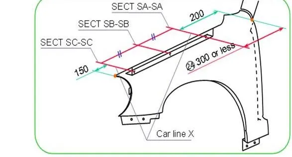
(2) at Hood Opening Condition the min Space for electric tooling Machine Should Be Min 200 mm To Fix Nuts And Bolts To Fender
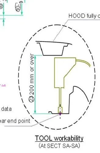
Also there are so many More Things Which We should Follow While Designing The Fender
also main thing is we need to follow the master section while designing the hood
for this challenge they have provided master sectiuon but in industry level we only mneed to create master section and need to follow it like on which side we need to thicken the component.....
Fender technically has 5 major mounting points, they are;
- Body mounting
- Sill mounting
- Cowl mounting
- A-pillar mounting
- Drip area mounting
Parts Navigator
Curve on Surface
Projected Curve
Extend
Extrude
Extract Body
Trim Sheet
Law of Extension
Dart
Emboss
Face and Edge Blend
Study of Fender Design Parameters :
- It is the area through which fender is attached to engine housing through fasteners.
- There should be some consideration followed to design the drip area of fender.
- From back side of front fender, there will be 200mm clearance for cowl(wiper motor) mounting area.
- From front side of front fender, there will be 150mm clearance for head lamp housing unit.
- Remaining area we can use to design a drip area.
- Height of fender can be minimum 80mm for child and adult (94mm,WAD 1700MAX, this +14 for increase in inertial force due to accident) impact.
- Parting will minimum 5 not more than 50mm from SRL ( a reference line on HOOD side, a point on fender makes from a line of 45 degree from ground level ).
- Drip area will not reach the engine assembly due to restriction of 40mm length, so there will some L-Shaped Bracket to connect with it.
ISO VIEW
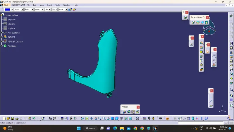
FRONT VIEW
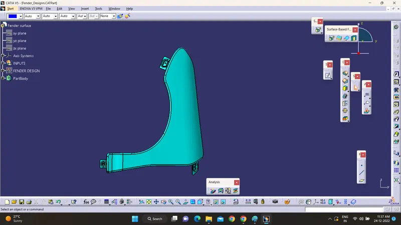
SIDE VIEW
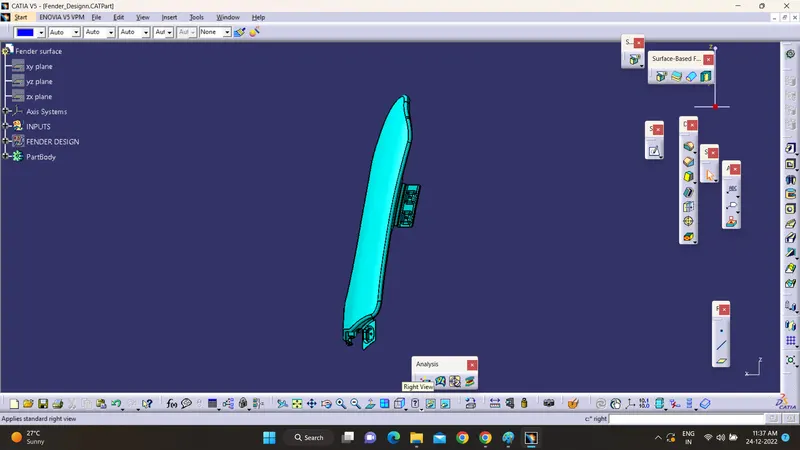
TOP VIEW
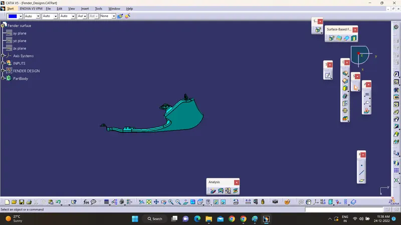
hello sir i have shared both stp file and cat file to you but i am getting some info that open cat file in desk and relocatye it
if file does not opens let me know sir....