Fender Design
FENDER DESIGN
OBJECTIVE
The main objective of this project is to design a fender using a new age design software-NX-CAD
INTRODUCTION:
Aluminum automotive components made using a hot blow forming process are reducing vehicle weight and increasing the fuel efficiency of today’s cars. However, before General Motors (GM) and the Department of Energy (DOE) sponsored research in this technology, blow forming of aluminum was not a viable process for automakers. The prior blow forming process called superplastic forming (SPF), was not suitable for the industry’s high-production-rate demands, and the materials required for SPF were too expensive three times the cost of standard, non-SPF, aluminum sheet metal. Therefore, bringing SPF to the automotive industry required developing low-cost SPF alloys and faster forming cycles. Reducing the cost of SPF alloys also required demonstrating the viability of SPF to both the automotive and aluminum industries. DOE initiated a program of joint-funded research between GM and Kaiser Aluminum, with the Pacific Northwest National Laboratory (PNNL) providing a catalyst to encourage GM to develop aluminum blow forming processes. Based on early research, General Motors recognized the inherent limitations of superplastic forming and moved forward with the commercialization of an advanced blow forming process, called Quick Plastic Forming. The result is cost effective, higher-volume manufacturing technology that is producing lightweight components for today’s automobiles. With the recognition of environment, all the governments have the strict standard of the letting epilogue. So, reducing the heavy is becoming the key of automobile development. One of the means of reducing the heavy of automobile is using the aluminum alloy and magnesium alloy. Aluminium, for its low density compared to steel, is the most promising material for achieving weight savings in future automotive body structure. Aluminum alloy has larger spring back and the lower plasticity; all of characters are difficulty for the stamping of complex shape of aluminum alloy car. As well known, Aluminum alloy is one of the superplastic materials which have longer elongation and no spring back under the superplastic state . These advantages of superplastic forming (SPF) process are the possibility to realize very complex part in one single operation and the low tooling costs . According to the capability of aluminum alloy and the advantages of SPF, a study of Finite Element Analysis (FEA) of superplastically formed front fender of aluminum alloy has been carried out. Considering the cost of the formed part, a commercial aluminum alloy sheet 5182 i.e. its material properties, which are used in FEA of stamping process of car panels, is selected as analytical material. The front fender of an all aluminum micro car . The dimension of the front fender is 916mm×181mm×710mm.
FENDER
The fender acts as a housing for the wheel and protects everything else by keeping the dirt and debris contained within the curved enclosure. This prevents the particles from spewing or damaging car parts on the car’s underbody and even other vehicles driving by.
Remember that all your car's tyres grip the road and turn forcefully to propel the car. But, as it does that, it also grips sand, tiny rocks, branches, and everything else, throwing it upward as it turns. That would be very damaging to the car and hazardous to other road users too.
TYPE OF FENER
There are two type of fender , They are
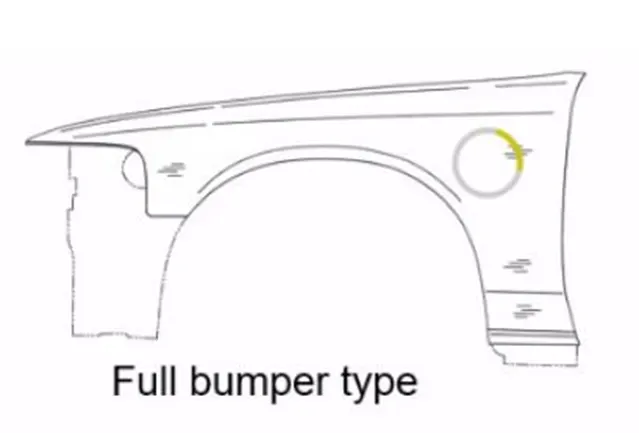
1 full bumper type
2 half bumper type
FULL BUMPER TYPE
HALF BUMPER TYPE
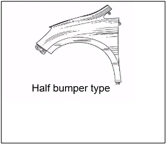
A fender is different than a bumper because it's a metal structure that frames the wheel well of your car, instead of the front or back. The fender extends between the front door to the front bumper covering the front wheels of the vehicle.
ASSEMBLY:
There are two type of assembly ,
1 bottom- up assembly
2 top-down assembly
BOTTOM-UP ASSEMBLY
Bottom-up assembly modelling is a part-centric modelling method where the assembly design is started with a principal structural or functional element, and individual parts are designed in relative isolation from the overall assembly.
TOP-DOWN ASSEMBLY
In top-down assembly design, one or more features of a part are defined by something in an assembly, such as a layout sketch or the geometry of another part. The design intent comes from the top, which is the assembly, and moves down to the parts.
MOUNTING REGIONS ON FENDER:
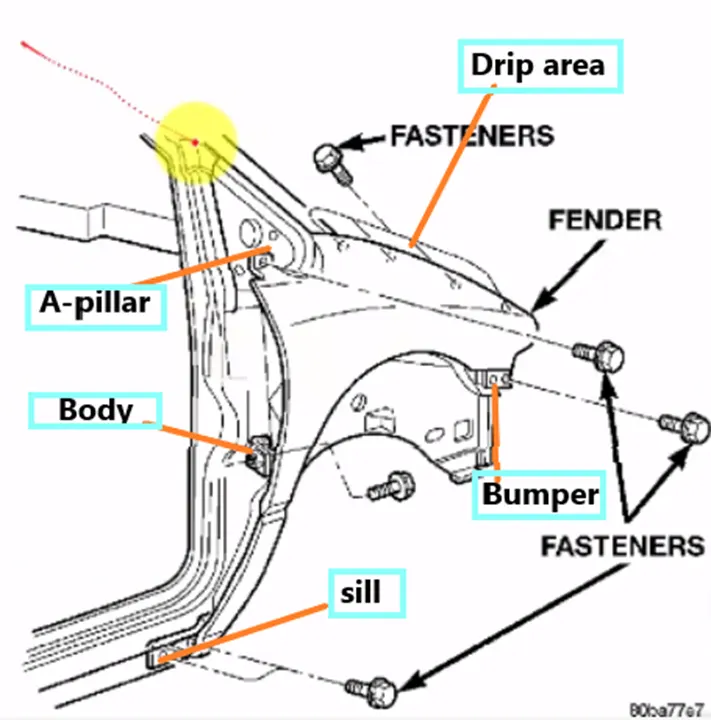
There are five mounting region on a fender ; they are
- A-PILLAR MOUNTING
- BODY MOUNTING
- SILL MOUNTING
- BUMPER MOUNTING
- DRIP AREA MOUNTING
DESIGN METHODOLOGY:
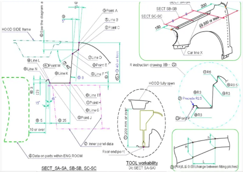
DESIGN OF DRIP AREA MOUNTING :
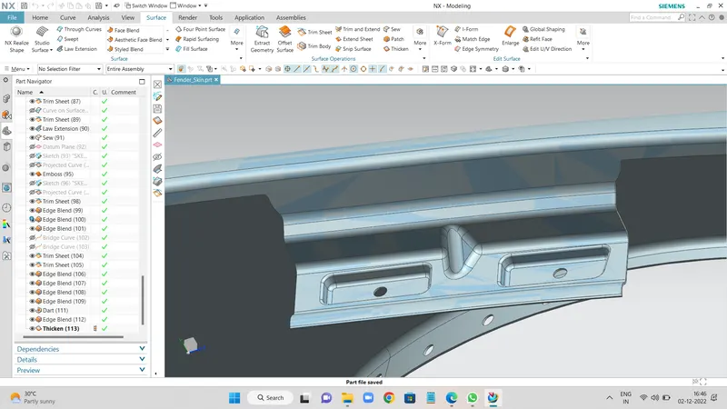
- It is the important uni of the fender. It is connected with the engine compartment , therefore the lot of design constraints are to be followed while designing the fender.
- While designing the drip we have to initially leave 200-300 mm for cowl top
- For placing the headlamp we have to leave at least 150 mm at the front while designing the fender
- Cowl top part consists pf wiper motor and its instruments.
DESIGN OF SILL MOUNTING AREA :
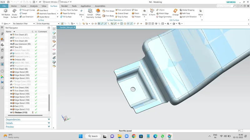
Sill is the panel directly below the bottom of the door supporting the floor and may be used to combine the floor and the body . the bottom end of the fender is mounting on the sill body for reinforcement of the fender panel ,thus the sill mounting position is designed with holes and emboss , M5 fasteners are used to fix the fenders on the sill body .
DESIGN OF BUMPER MOUNTING AREA: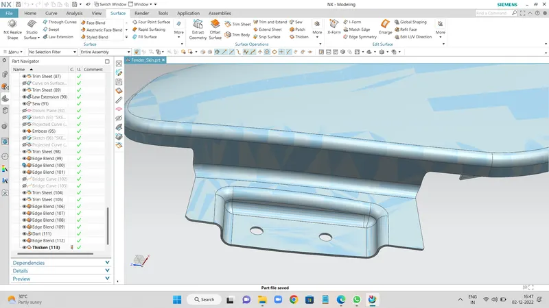
DESIGN OF A-PILLER MOUNTING AREA :
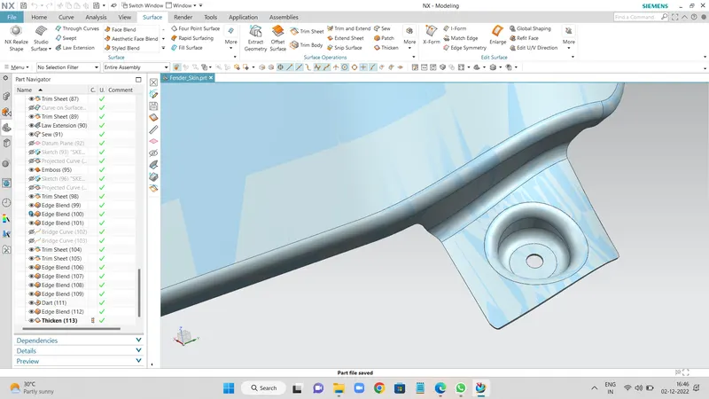
DESIGN OF A-PILLER MOUNTING AREA :
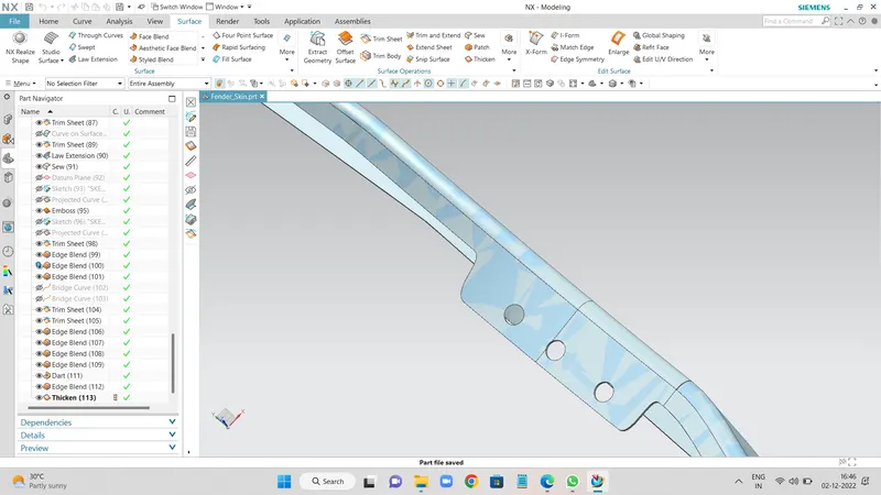
APPLYING OF THICKNESS TO THE SURFACE .
The thickness of 0.75 mm inward on the final sewed surface of the fender to the sheet metal parameters
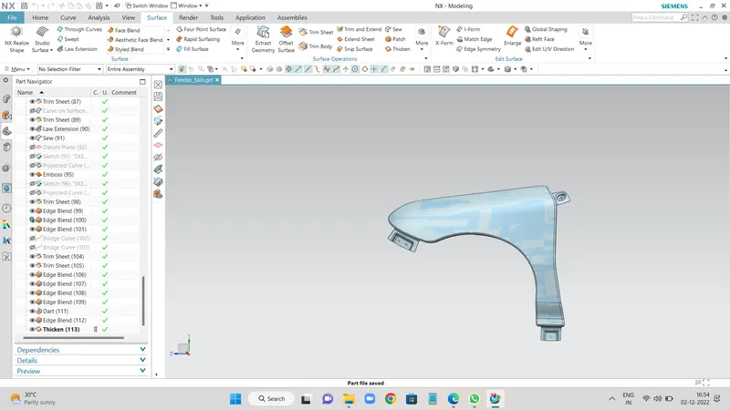
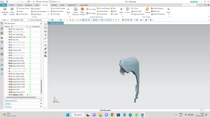
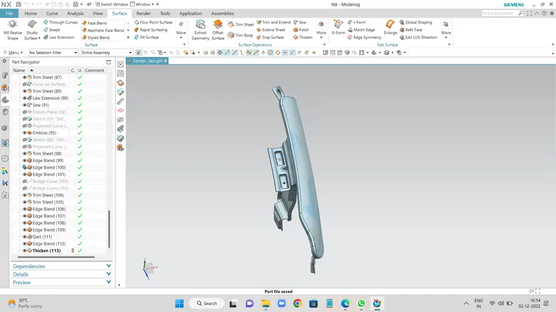
DIFFERENT VIEWS OF FENDER :
CONCLUSION :
Finally design of fender is done with the help of NX-CAD software by following the master section