Fender Design
FENDER DESIGN
OBJECTIVE:
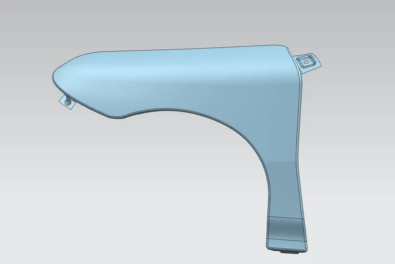
The main objective of this project is to design a fender using a new age design software NX-CAD
INTRODUCTION:
Design of any product starts from an requirement. The design engineer sketches the product based on the requirement. Then the 2D sketch with the proper dimensions is converted into 3D model using the advanced CAD software. The another important thing in the design is that, every product that is designed should be able to manufacture. So the role of the design engineer is to design the product that can be easily manufactured and with less cost effective. This is the place where the design for manufacturing [DFM] and Design of assembly [DFA] takes a role while developing any product. The process of developement of design carries on untill the design satisfies the customer needs. Here in this project the product that we are going to develop is a car fender.
DESIGN OF CAR FENDER:
Fender is the part of an automobile, motor cycle or other vehicle body that frames a wheel well. Its Primary purpose is to prevent sand, mud, rocks, liquids and other road spray from being thrown into the air by the rotating tire. Fenders are typically rigid and can be damaged by contact with the road surface.
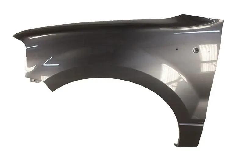
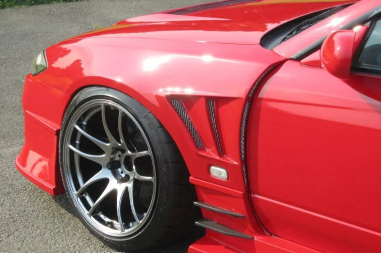
Sticky materials , such as mud, may adhere to the smooth outer tire surface , while smooth loose objects such as stones, can become temporarily embeded in the tread grooves as the tire rolls over the ground. These materials can be ejected from the surface of the tire at high velocitiy as the tire imparts kinetic energy to the attached objects. For a vehicle moving forward, the top of the tire is rotating upward and forward, and can throw objects into the air at other vehicles or pedestrians in front of the vehicle.
TYPES OF FENDER:
There are two types of fender, they are:
1. Full Bumper type
2. Half Bumper type
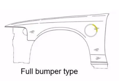
FULL BUMPER TYPE: These types of fender were used in earlier models of vehicles. They contribute to the major increment of the steel weight by just covering the front headlights with respect to the bumper region. The problem associated with this kind of fender is there is a lot pf wastage in the blank and every inch of a material is a cost of the industry.
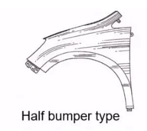
HALF BUMPER TYPE: These fenders are mainly usedfor serving he purpose of cost cutting and reducing enough proportions of the steel wait resulting in a reduction of the weight of the veicle slightly. They can be economically manufactured, i.e. by slightly increasing the blank size, we can produce two fenders at a time.
Areas to consider while designing a fender:
- Drip area
- Bumper mounting area
- Sill mounting area
- A pillar mounting area
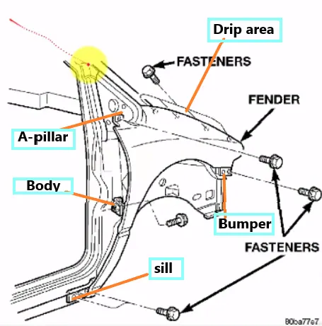
DRIP AREA:
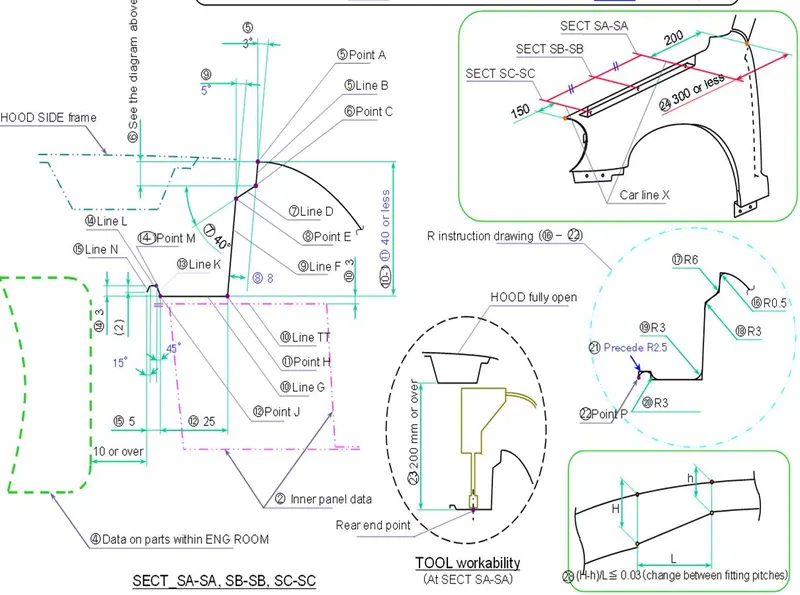
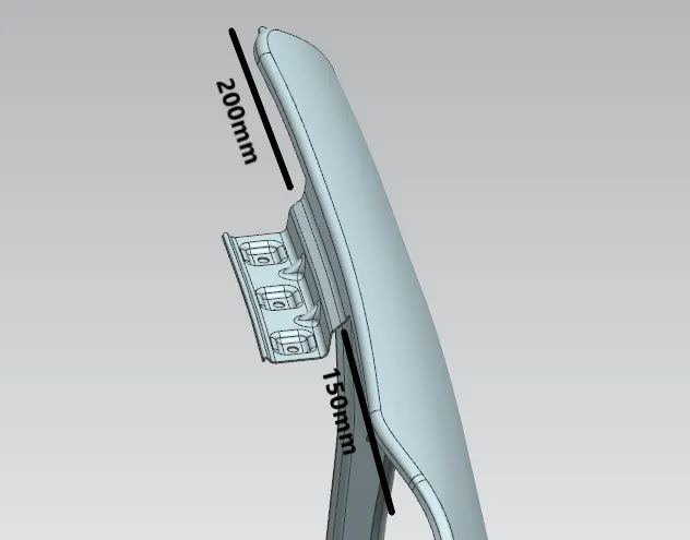
It is the important part in the fender. This mounting is attached to the engine compartment of the car. Fender drip area is mounted via weldnuts to the engine compartment. A min of 150 mm distance is kept from the front side and a distance 300 mm or less can be kept on the rear side. The total lenght of drip area from the top of fender should be less than 40 mm, this is to avoid the springback during the manufacturing. The edge of the mounting should atleast be 10mm away from any nearby component in the engine. A rigidity bead is provided at the end to increase the strenght of the mounting.
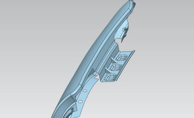
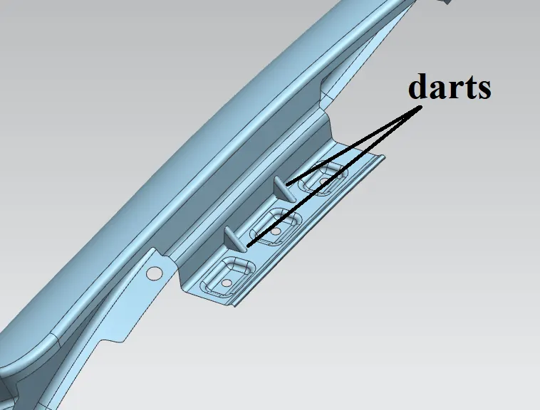
Darts are provided at the bends to stiffen the sheet metal at that region.
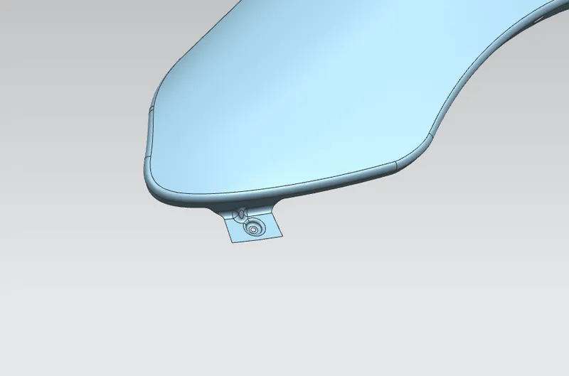
BUMPER MOUNTING AREA:
The bumper mounting region is located beneath the bumper. The fender gets attached before the installation of the bumper. After fixing the fender with fastenersthe bumper will cover the bumper mounting.
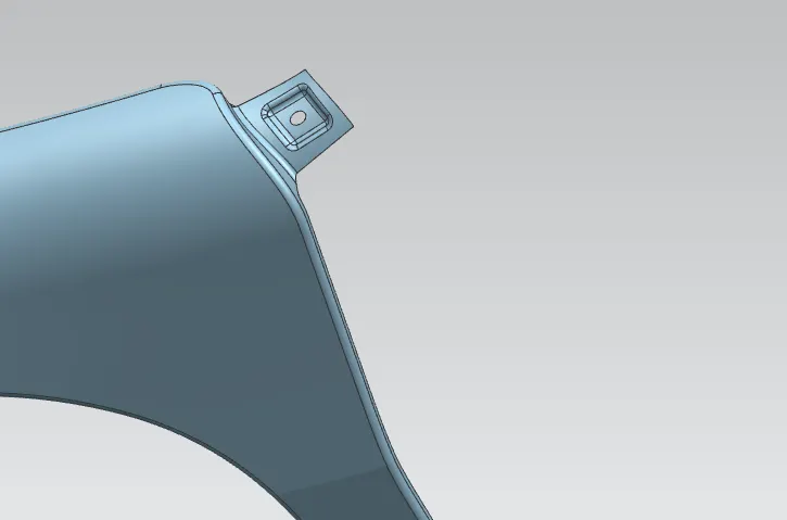
A PILLER OUNTING AREA:
This mounting region is located near the cowl of the vehicle where the fender is fastened wth the bottom edge of the windshield. This mounting is covered with the side rear view mirror.
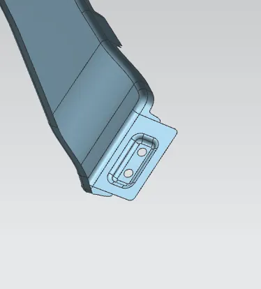
SILL MOUNTING AREA:
The area at which the bottom of the fender gets connected to the floor near the bottom edge of the door. The embossed sill mounting of the fender is attached with the fasteners.
DESIGN PROCEDURE:
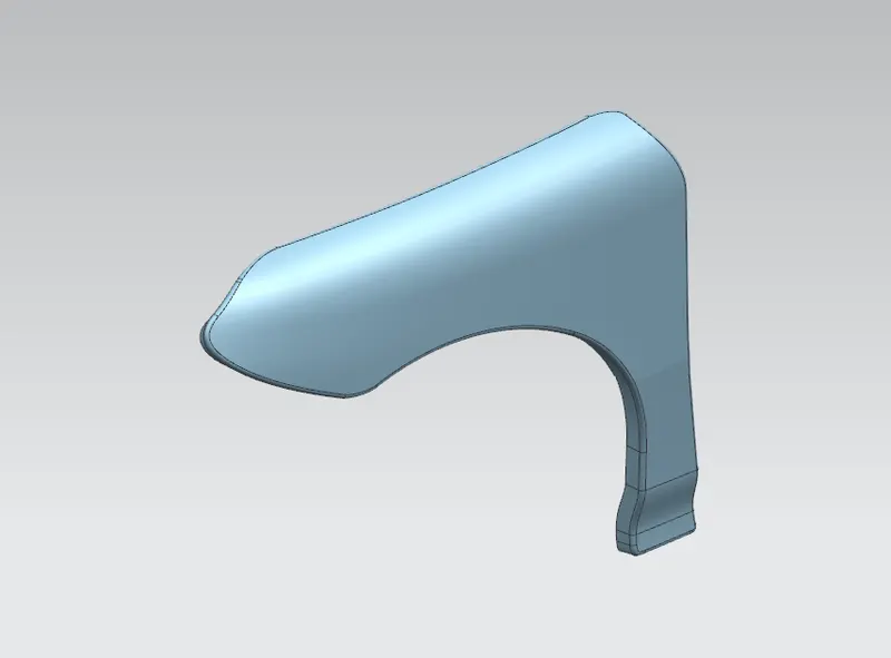
Input- We have the outer skin of the fender as our input.
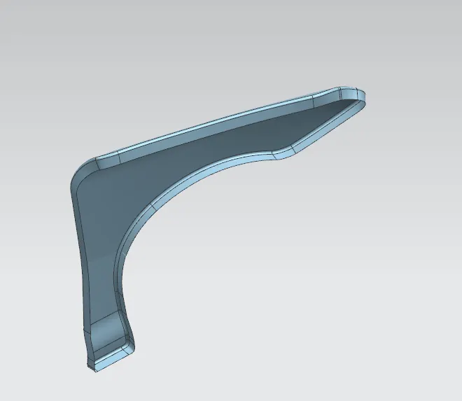
1) Drip area-
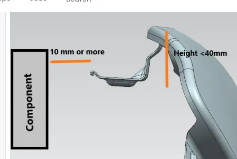
- The height of drip area mounting should be less than 40mm so that it reduces the springback effect during manufacturing.
- The edge of the mounting part should be atleast 10mm away from the nearby components in the engine.
- it should be distanced atleast 150mm from the front side and 200mm from the rear side.
- Ribs should be provided in order to increase the strength of the mounting part.
- Beads is provided at the outeredge to increase the rigidity of part.
2) A-Pillar -
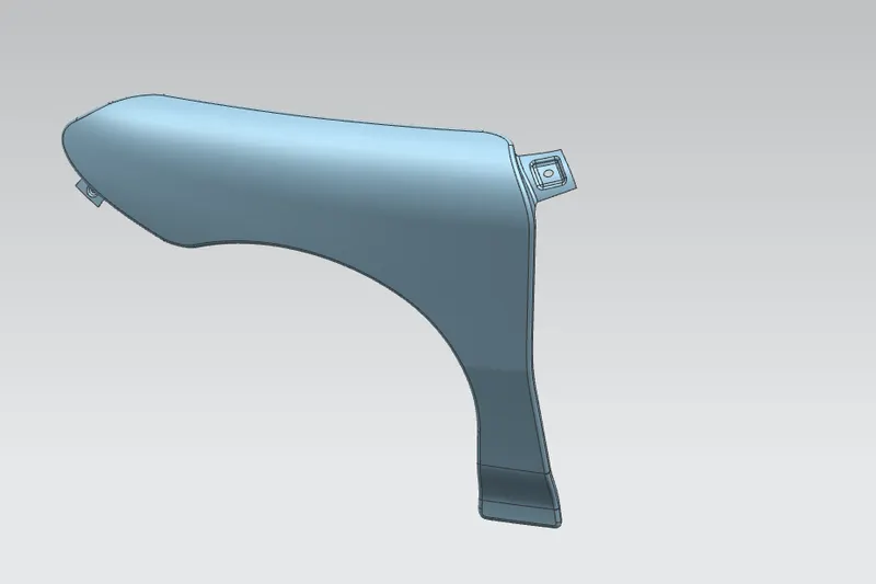
- Ribs are provided n order to increase the strength of A-pillar mounting point
- Other factors for the mounting flange will depend upon the A- pillar design of car.
3) Bumper side-
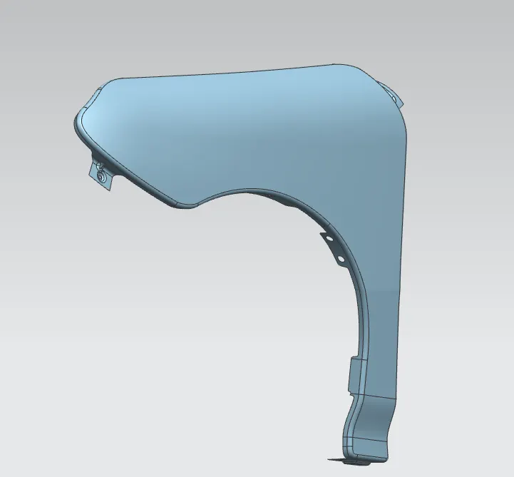
4) Sill area mounting-
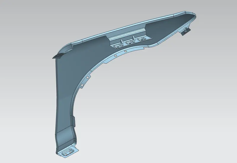
5) Baffle mounting-
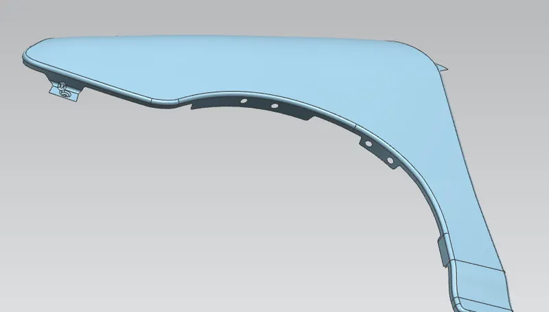
- For mprovement of NVH in car, usually a baffle is moounted on the fender of the car. It is mounted on the wheel arch area.
Output-
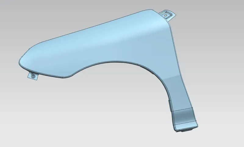
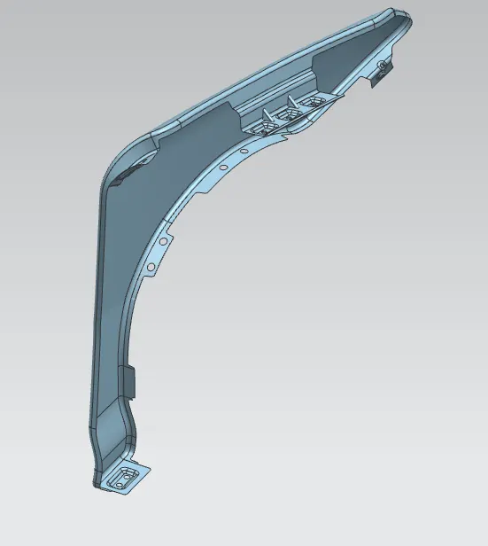
CONCLUSION:
The fender is designed with the necessary mounting points considering the design parameters. We have developed front fender with mounting points following the design parameters and mastersection.