Fender Design
Fender:
It is the part of an vehicle body that frames a wheel well. Its primary purpose is to prevent sand, mud, rocks, liquids, and other road spray from being thrown into the air by the rotating tire. For a vehicle moving forward, the top of the tire is rotating upward and forward, and can throw objects into the air at other vehicles or pedestrians in front of the vehicle.
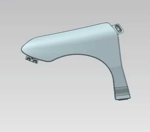
There are two types of fender
1) Full bumber type fender,
2) Half bumber type fender.
Different Mounts in Fender:
There are five mounting Points in a fender,
- Body Mounting
- A pillar Mounting
- Sill Mounting
- Cowl Mounting
- Drip Mounting
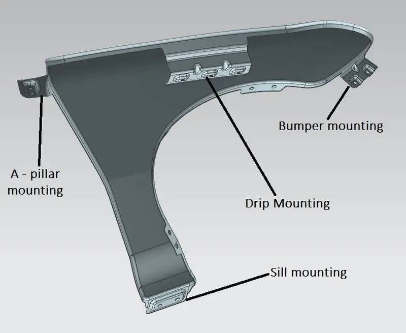
Drip Mounting area:
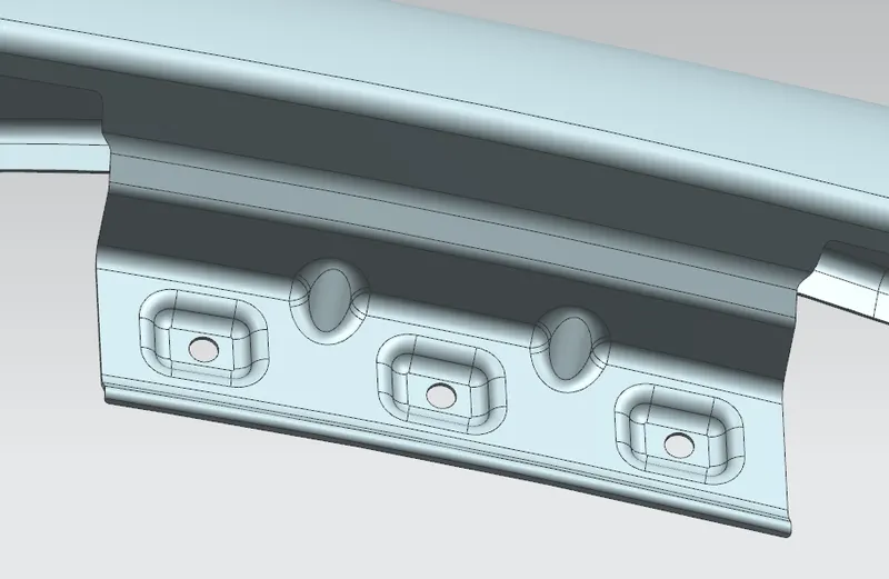
Drip mounting is connected with engine compartment through fasteners. Drip mounting section created as per mastersection given.
Sill mounting area:
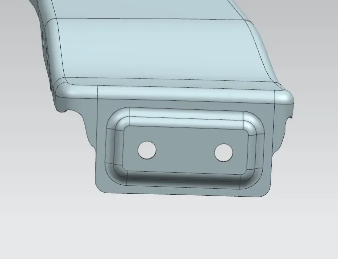
A pillar mounting area:
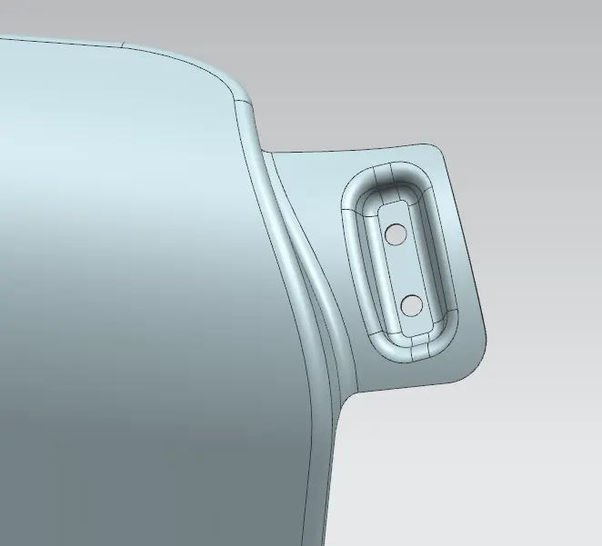
Bumper mount area:
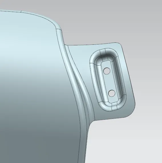
Baffle mount area:
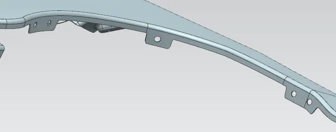
Manufacturing process:
The manufacturing process includes the following steps,
- Initially unfolding and shearing are carried out on a plate, wherein a proper cold roll specification is selected at first, a cold roll is unfolded, and then the unfolded cold roll is sheared to an iron plate of the corresponding size according to production material specifications.
- Secondly, oil pressing and punching are carried out, wherein the iron plate is extended at first, then side shearing and punching are conducted on the iron plate, folding and shaping are carried out on the iron plate, and finally reshaping is carried out on the iron plate.
- Thirdly, small first parts of the fender are machined, wherein first of all, the iron plate is punched to a needed outer contour blank, then the iron plate completing the outer contour blank is further shaped, and the iron plate is punched at last.
- Fourthly, installation and welding of a metal plate are conducted. The manufacturing process for the car fender is simple and high in production efficiency; a body of the fender and the small parts can be separately machined, so waiting time is shortened; working efficiency of production is improved.
Design parameters:
Fender drip area:
Drip depth shall be uniform A=B=C,
Drip area specifications are given in the mastersections. in drip area the height must be 40 mm or less as maximum productivity is achieved at this distance. If depth exceeds 40mm, rigidity bead is to be provided. Also forming is not feasible if depth exceeds 60mm due to wrinking and spring back effect. For avoiding spring back effect we have to give dart in the drip area, It will give more rigid to the part and prevent from vibration of the component.
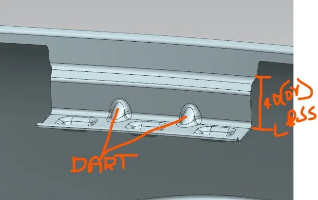
Also follow regulations of wheel arch of different region, we are following european regulation. So from wheel to fender we have to maintain 10mm distance.
Conclusion:
Fender mountings were created for different mounting areas, Also follow the mastersection for creating drip area. Also give dart for strengthening the drip and bumper mounting area. Finally thicken the component to 0.75mm.
Thanks