Fender Design
FENDER DESIGN
INTRODUCTION
- What is fender?
- Types of fender
- Mounting regions
- Manufacturing methods
- Design consideration
- Design of fender
FENDER
A fender is the part of a car, truck, motorcycle, or other vehicles that frames or covers a wheel well. Its main purpose is to prevent debris, rocks, mud, liquids, sand, and other road debris from getting thrown in the air while the tires rotate.
TYPES OF FENDER
The type of fender is based upon the area covered i.e. full fender type and half fender type.
- Full bumper fender
- Half bumper fender
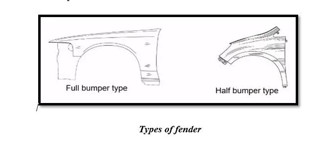
- Full Bumper fender
This type of bumper is not commonly used because this design is more scrap producing one during manufacturing. The blank of steel or aluminium used to produce this type has more wastage. This type is not economically good to manufacture.
- Half Bumper Type:
This type of fender is most commonly used. The cons of full bumper type are satisfied in this design, and the blank area of wastage while producing the part is drastically reduced by scrap management.
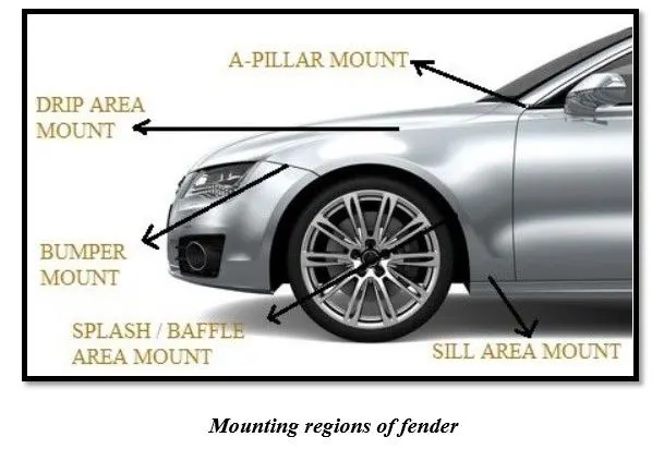
MOUNTING REGIONS:
- Drip area mount
- A- pillar mount
- Bumper mount
- Sill area mount
- Cowl area mount
MANUFACTURING METHODS:
Manufacturing process for automobile fender, comprises the following steps:
Step 1: open straight snips plate: first select applicable cold coiling specification, cold coiling is opened flat; then according to production material specification, will open cold coiling after flat and be cut into the iron plate of corresponding size; finally the iron plate after shear is cleaned to iron filings.
Step 2: oil pressure, punch press: first iron plate is extended, Secondly to its trimming and punching. Then to its flanging and shaping, finally after shaping completes, then carry out one-off hole-piercing, completed the making of lappet plate body.
Step 3: smallclothes of processing lappet: first iron plate is stamped out to required outline blank (blanking); Then to completing the further moulding of iron plate of outline blank, Finally it is carried out to punching.
Step 4: panel beating assembly welding: first smallclothes are carried out to spot welding M6 nut; then part point is welded on lappet; finally lappet body and smallclothes are carried out to sanding thorn and ending.
Step 5: All the plastic parts are produced by injection moulding.
DESIGN CONSIDERATION:
DESIGN OF DRIP MOUNTING:
- While designing drip area mounting parameters should be considered i.e., 200 mm or less from A pillar region.
- All the other fitments assembly (wiper motor, head lamps, indicators, engine compartment etc.,) considerations should be taken into account while designing the mounting position along the length.
- While providing the angular dimensions for mounting care should be taken that mounting bolts are properly hidden from normal viewing line.
- Ribs should be provided for improving the strength of the mount.
- Flat surface should be maintained at the contact patch of the mount.
- Draft angle should be considered for designing and contact patch around the hole should be at least 5 mm.
- At the extreme edge of the mount blend is performed to avoid vibrations and spring back effect.
DESIGN OF BUMPER MOUNTING:
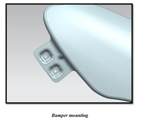
- It connects the fender with the bumper of the automobile with the help of fasteners.
- At the mounting the surface should be maintained flat.
- Based on the design darts should be provided to inculcate the strength.
DESIGN OF A-PILLAR MOUNTING:
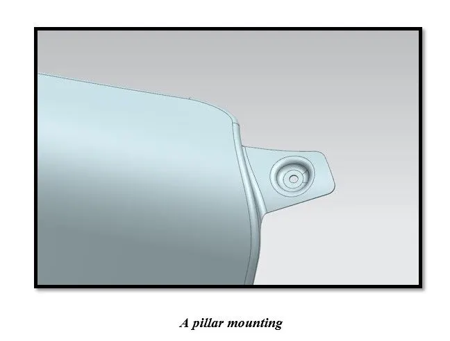
- It connect fender to the A- pillar of the automobile which connects to the roof.
- Flat surface is maintained at the mounting.
DESIGN OF BAFFLE MOUNTING:
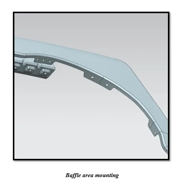
- Baffle mountings connects the fender and baffle/splash at inner region which protects the automobile as well as pedestrians from chip out debris on the road when the automobile in motion. Wheel arc is taken into consideration for pedestrian safety as per the regulations.
DESIGN OF FENDER:
Aim:
To design a Front Fender from the given skin data and the Master Section provided with Drip Mounting, A-Pillar, Sill, Bumper and Baffle (splash) Mounts.
Software used:
Siemens NX 12
Design parameter:
Master section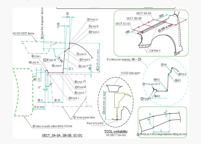
Procedure
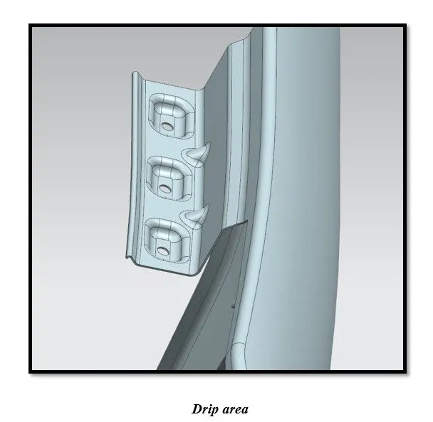
Drip Area:
- The area at which the fender gets attached to the engine housing through fasteners. It is the major mounting for the fender.
- The height of drip area mounting should be less than 40mm so that it reduces the spring back effect during manufacturing.
- The edge of the mounting part should be at least 10mm away from the nearby components in the engine.
- It should be distanced at least 150mm from the front side for the headlamp housing unit and 200m from the rear side for the cowl setup.
- Darts should be provided to increase the strength and to increase the rigidity of the mounting part.
A-Pillar Area:
- This Mounting region is located near the cowl of the vehicle where the fender is fastened with the bottom edge of the windshield. This mounting is covered with the side rear-view mirror.
- Ribs are provided to increase the strength of the A-Pillar mounting point.
- Other factors for the mounting flange will depend upon the A-pillar design of the car.
Bumper Area:
The bumper mounting region is located beneath the bumper. The fender gets attached before the installation of the bumper. After fixing the fender with fasteners the bumper will cover the bumper mounting.
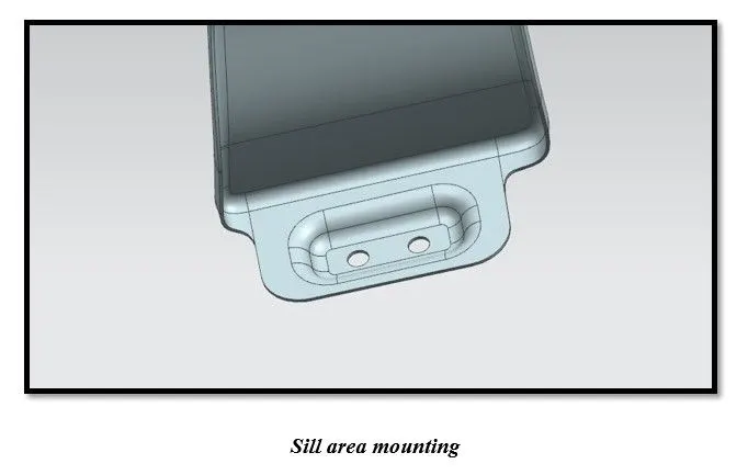
Sill Area:
The area at which the bottom of the fender gets connected to the floor near the bottom edge of the door. The Embossed sill mounting of the fender is attached with the fasteners.
Baffle Area:
- In this region, the baffle gets installed to the fender with the help of clips which holds the baffle with the fender along the wheel arch.
- For improvement of NVH in car, usually, a baffle is mounted on the fender of the car. It is mounted on the wheel arch area.
Result:
Working on Fender Skin data was done such as for the creation of all the above mounting points, considering all the design considerations required and following the master section. The above images show the mounting points created and the final look of the fender after the thickening operation.
Conclusion:
Hence, according to the Engineering standards the Sill, Bumper, Baffle (Splash), drip area and A-Pillar mount has been created using Siemens NX 12.