Fender Design
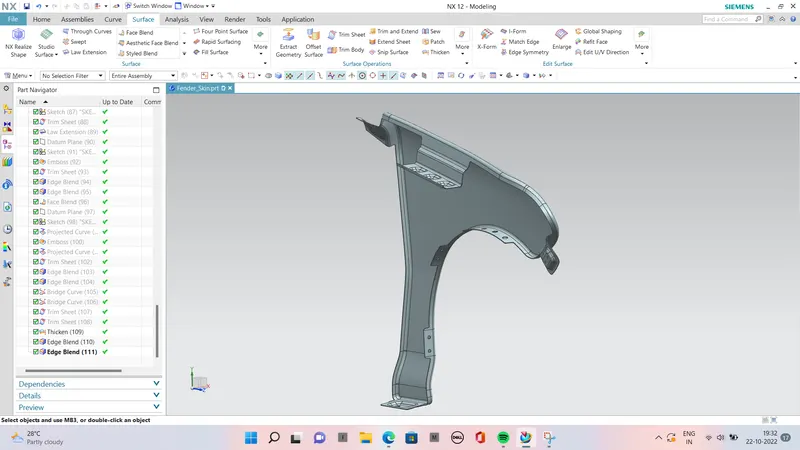
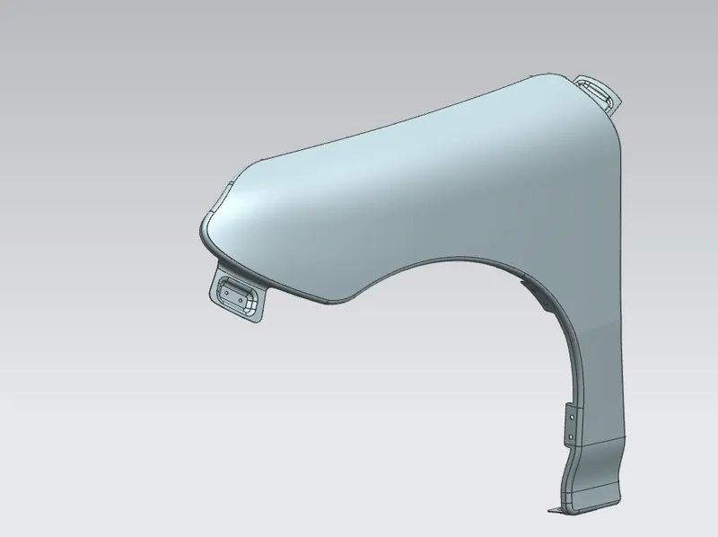
The main objective here is to design Drip area, Bumper mounting region, Sill mount region, A-Pillar mount region and Splash cover or wheel well mount regions for the given fender skin or styling surface.
.The Importance of car Fenders :

.The fenders are an intricate sheet of metal covering the wheel well of your car.

Fenders are designed in a manner to  provide resistance against wind and other roadside debris.

.When you travel on rough terrains tour vehicle might get minor scratches and dents which look no better. Frequent road bumps can cause your cars paint to chip off which needs a paint job done.

.The car fender are located on either side of the front and rear wheels. The front car fenders begin where the front door hinges run and end just before the bumper. The rear car fenders begin where the back doors close and terminate before the back bumpers.
Types of Fenders :

.There are two types of fenders.

1Full Bumper Type
2.Half Bumper Type

Full Bumper Type :

.This type of bumper is not commonly used because this design is more scrap producing one during manufacturing. The blank of steel or aluminum usedto produce this type has more wastages. This type is not economically good to manufacture.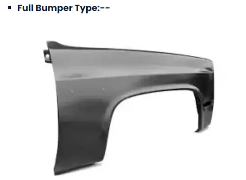
Half Bumper type :

This types of fenders most commonly used. The con's of full bumper type is satisfied in this design, and the blank area of wastage while producing the part is drastically reduced by scrap management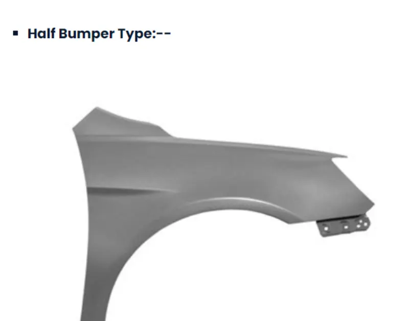
Purpoes of Fender :

Cleanliness :  Protect the car, occupants and passers by from items, water, mud, snow, ice, thrown off the tires as you drive.

Safety : Protects pedestrain from the wheel, e.g. its better to be it by a laterally moving fender than a rolling tire, keeps loose, streaming items from being wrapped up in a rolling wheel.

Aerodynamics : Smooths the car profile so you don't get a lot of drag off the uncovered wheels. Some fenders are enclosed on the side for this.

General Appearance : Looks better with fender,  gives a finished look, looks more streamlined.

Front Fender Desing :

The given master section to  create the drip area and for the still mount, Bumper mount and A-pillar mount create your own design according to the engineering standard.

Drip Area

Sill Mount

Bumper Mount

A Pillar Mount

Splash/Baffle Mount

Design of Drip Mount Area :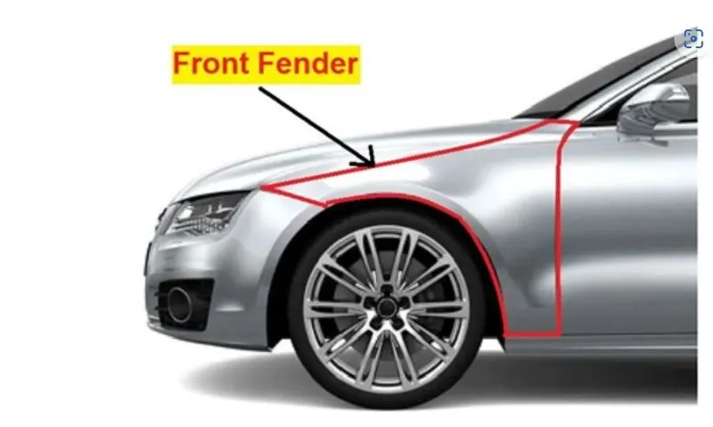
DESIGN CONSIDERATIONS
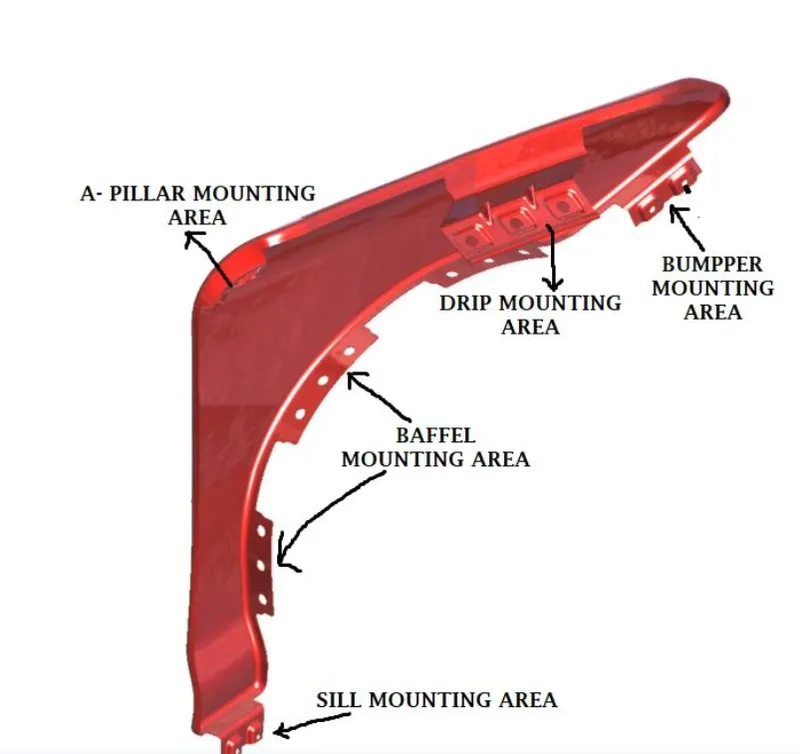
The front fender has basically five mounting positions with respect to the other components. The mounting positions are as follows:
Drip Area Mounting.
A-Pillar Mounting.
Sill Mounting.
Bumper Mounting.
Baffle Mounting.
For the creation of the Drip Area Mounting, the given Master Section is followed, and the other mounting points are created by assuming appropriate positions with the respected components.
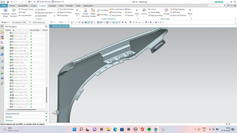
PROCEDURE TO CREATE DRIP AREA :

While designing the drip area, a 150mm clearance is maintained from the front-end for headlight fittings and 200mm clearance from the rear-end for the wiper motor assembly (Cowl top area)
The depth of the drip area is maintained at less than 60mm so as to avoid the spring-back effect.
Ribs are provided at the fender drip area to increase strength in that area.
STEP 1 : First we have to create an Offset of the curve.

STEP 2 : Use law extension from the given flanges of the fender following the master section.

STEP 3 : Give face blends to all the law extended flanges.

STEP 4 : Sketch the mounting area face and holes of 5 mm dia, holes should have 10mm dia flat surface.

STEP 5 : Project the sketch on the drip area surface.

STEP 6 : Create a datum plane to give emboss to that respect.

STEP 7 : Create an emboss using the dtatum plane.

STEP 8 : Trim sheet for holes.

STEP 9 : Give face blends to emboss.

STEP 10 : Give edge blen and make sure there are no any sharp edges and should have smooth transition of surfaces.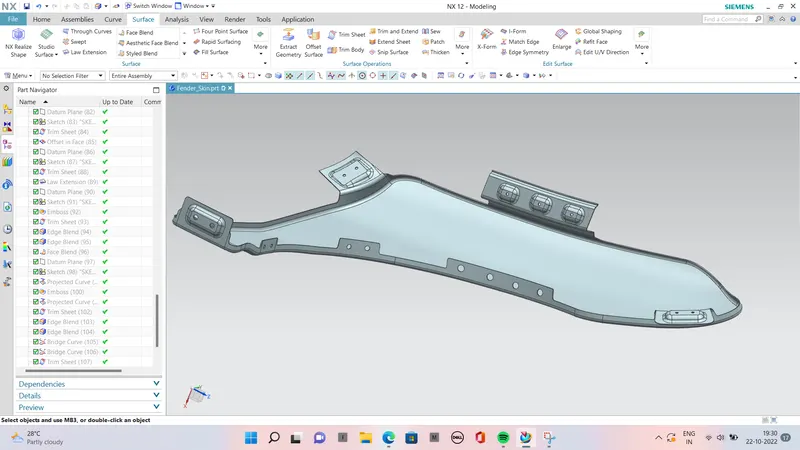
Design Criteria :

Embosses are provided to increase the strength.

Smooth curves are designed for easy manufacturing of panel.

Ribs are provided to drip area mount to give structual support and extra strengh.

Maintain extra 10mm from the flat surface  for the fastner holes.

All fillets should maintain 2 or 3mm radius in most regions.

Thickness of fender is 0.75m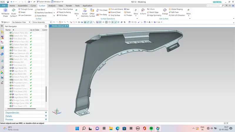
DIFFERENT VIEWS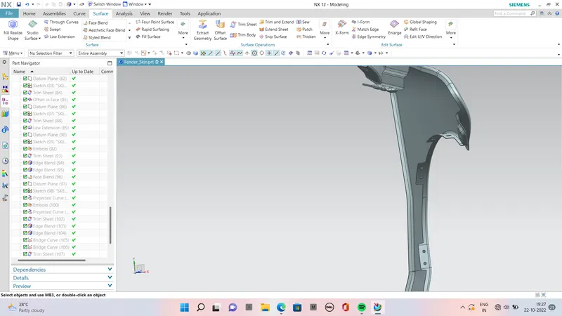
1. Baffle Mounting: These mounting points are created for attaching plastic components i.e baffle which prevents chipping inside the engine compartment.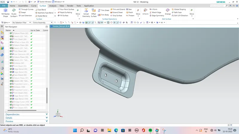
2. Bumper Mounting: This mounting point is created for attaching the bumper to the fender. It should have enough strength to hold the bumper steadily.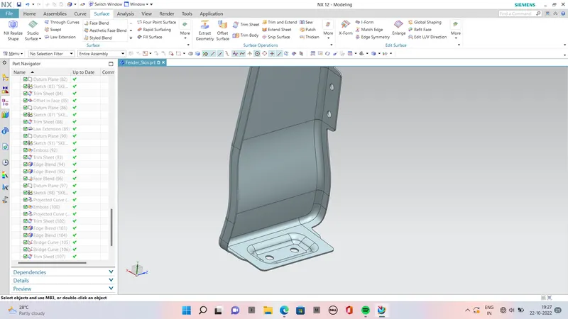
3. Sill Mounting: Sill mounting is created on the bottom portion of the fender for attaching to the sill.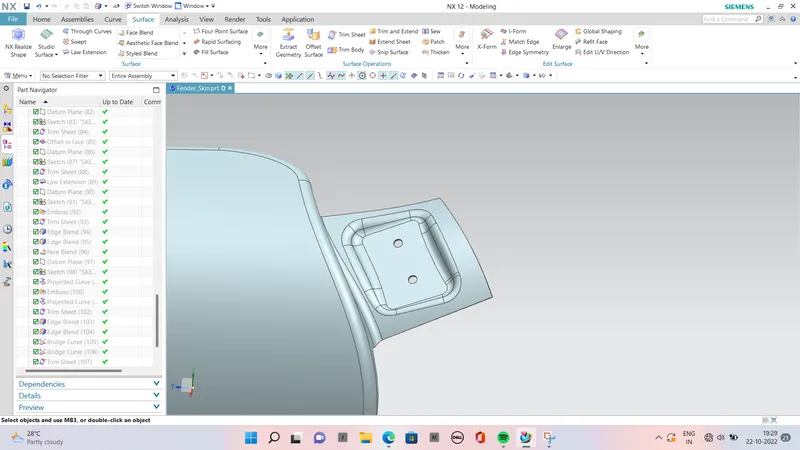
4. A-Pillar Mounting:

This mounting position is created for attaching the fender to A Pillar of the vehicle.
The mounting has to be created by taking the reference from the A-pillar of the vehicle.
Enough clearance should be given for the easy mounting of the wiper equipment.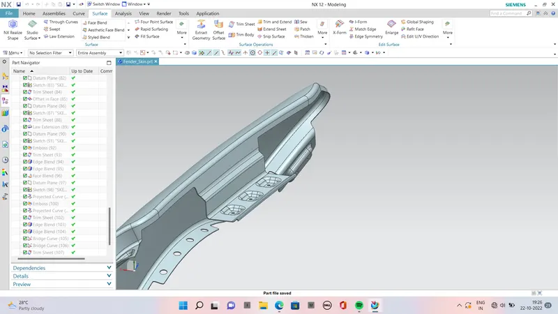
5. Drip Area Mounting:

The drip area is the most important mounting in a fender, it is the point where the fender has to be attached to the engine compartment.
The drip area should be designed in such a way that it should be at least 150mm away from the front end of the fender to have sufficient space for mounting headlamps housing.
Mostly the drip area starts from 200mm away from the rear end of the fender, to have sufficient space for the cowl which carries the wiper equipment.
The length of the drip area depends on the length of the fender.
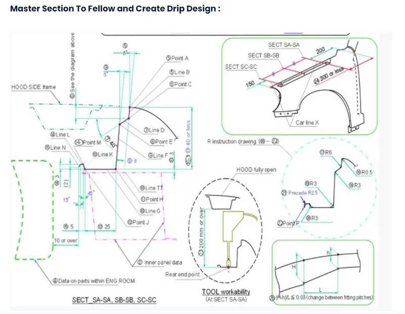
It is most important mounting unit of a fender. Its connected with the engine compartment and therefore a lot of design constraints are to be followed while designing the drip area. It should have sufficient clearance from the front and rear end of the  fender to accommodate  the cowl mounting region  and the  headlamp housing unit respectively.

From the master section we have optimize value for draft , drawing and assembly point  to view. Such as distance from the engine comportment is 10mm, height of fender etc.

Design Criteria :

Embosses are provided to increase the strength.

Smooth curves are designed for easy manufacturing of panel.

Ribs are provided to drip area mount to give structual support and extra strengh.

Maintain extra 10mm from the flat surface  for the fastner holes.

All fillets should maintain 2 or 3mm radius in most regions.

Thickness of fender is 0.75mm.
DESIGN CONSIDERATIONS
The front fender has basically five mounting positions with respect to the other components. The mounting positions are as follows:
Drip Area Mounting.
A-Pillar Mounting.
Sill Mounting.
Bumper Mounting.
Baffle Mounting.
For the creation of the Drip Area Mounting, the given Master Section is followed, and the other mounting points are created by assuming appropriate positions with the respected components.
1. Drip Area Mounting:
The drip area is the most important mounting in a fender, it is the point where the fender has to be attached to the engine compartment.
The drip area should be designed in such a way that it should be at least 150mm away from the front end of the fender to have sufficient space for mounting headlamps housing.
Mostly the drip area starts from 200mm away from the rear end of the fender, to have sufficient space for the cowl which carries the wiper equipment.
The length of the drip area depends on the length of the fender.t.
CONCLUSION:--
The Fender had been designed according to the given master section.
I have followed all the regulations while creating the part.