FEA Using SolidWorks Project 3 : Analysis on a plate with a hole
AIM :
Finite element analysis of a plate with hole.
Objective :
The project involves performing a static structural analysis using Solidworks simulation, on two models to find out and compare the deformation and maximum stress in two plates and their behaviour around stress concentration regions like holes.
Theory:
The entire process of performing a solidworks simulation can be divided into four parts.
1. Part design
Includes making the part file of the model to be analyzed and material assignment to the components.
2. Setting up of boundary conditions
Includes setting up the fixed supports, reactions and external loads.
3. Meshing
The type, size and various other mesh parameters are setup.
4. Solver Analysis
The solver is run giving out the results for Von mises stresses, strains and displacements at all the nodes and identifying the minimum and maximum values of those to determine the critical regions.
Simulation Process :
1. Models Design (Part Design)
The external block dimensions of both the plates are 300mmx120mmx30mm.
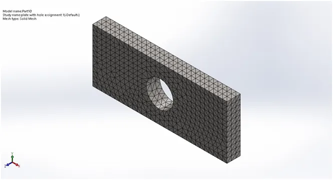
Case 1: Plate with a hole of 60 mm diameter in the centre as shown in the figure below.
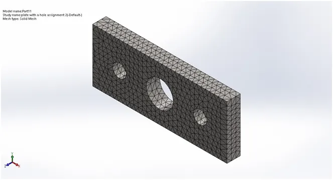
Case 2: Plate with 2 additional holes of diameter 30mm on either side of the main hole at 90mm from the centre
Material properties:
The material of both the plates is chosen to be Alloy steel, the properties of which are given in the below table. Name: Alloy Steel
Model type: Linear Elastic Isotropic
Default failure criterion: Max von Mises Stress
Yield strength: 6.20422e+08 `N/m^2`
Tensile strength: 7.23826e+08 `N/m^2`
Elastic modulus: 2.1e+11 `N/m^2`
Poisson's ratio: 0.28
Mass density: 7700 `{kg}/m^3`
Shear modulus: 7.9e+10 `N/m^2`
Thermal expansion coeficient: 1.3e-05 /Kelvin
2. Boundary Conditions :
Once the model has been developed, the next step is to establish fixtures and loads on the plates which are responsible for their deformation. The boundary conditions imposed on the plates are a fixture on one side and a load of 1000N on the other side - 120 X 30 mm surface.
Case 1
Case 2
3. Meshing :
Meshing of the plates is done successfully with the default mesh size and the meshed part is shown below.
CASE 1
MESH INFORMATION:
Mesh type Solid Mesh
Mesher Used: Standard mesh
Automatic Transition: Off
Include Mesh Auto Loops: Off
Jacobian points 4 Points
Element Size 0.0099862 m
Tolerance 0.00049931 m
Mesh Quality Plot High
Total Nodes 11535
Total Elements 7121
Maximum Aspect Ratio 2.949
% of elements with Aspect Ratio < 3 100
% of elements with Aspect Ratio > 10 0
% of distorted elements(Jacobian) 0
CASE 2
MESH INFORMATION
Mesh type Solid Mesh
Mesher Used: Standard mesh
Automatic Transition: Off
Include Mesh Auto Loops: Off
Jacobian points 4 Points
Element Size 0.00984229 m
Tolerance 0.000492114 m
Mesh Quality Plot High
Total Nodes 11310
Total Elements 6856
Maximum Aspect Ratio 3.6048
% of elements with Aspect Ratio < 3 99.9
% of elements with Aspect Ratio > 10 0
% of distorted elements(Jacobian) 0
RESULTS:
The results of the analysis performed are given in three plots with values at various nodes throughout the body. The maximum values of these indicate the critical node and thus the critical areas in the given model which is more prone to failure.
STRESS PLOT
CASE 1
Name Type Min Max
Stress1 VON: von Mises Stress 4.152e+04 `N/m^2` 1.187e+06 `N/m^2`
Node: 692 Node: 29
CASE 2
Name Type Min Max
Stress1 VON: von Mises Stress 1.311e+04 `N/m^2` 1.134e+06 `N/m^2`
Node: 747 Node: 9852
STRAIN PLOT
CASE 1
Name Type Min Max
Strain1 ESTRN: Equivalent Strain 2.738e-07 4.223e-06
Node: 714 Node: 3288
CASE 2
Name Type Min Max
Strain1 ESTRN: Equivalent Strain 5.045e-08 4.043e-06
Node: 1990 Node: 4437
DISPLACEMENT PLOT
CASE 1
Name Type Min Max
Displacement1 URES: Resultant Displacement 0.000e+00 mm 5.237e-04 mm
Node: 99 Node: 433
CASE 2
Name Type Min Max
Displacement1 URES: Resultant Displacement 0.000e+00 mm 5.658e-04 mm
Node: 176 Node: 10371
CONCLUSIONS:
S.No Quantity Plate with one hole Plate with three holes
1 Max Von mises stresses(`N/m^2`) 1.187e+06 1.134e+06
2 Max Strain 4.223e-06 4.043e-06
3 Max Displacement(mm) 5.237e-04 5.658e-04
The plate with a single central hole experiences higher maximum stress than the plate with three holes. This seems counter-intuitive at first since the plate in the second case has a higher number of stress concentration regions and hence expected to experience higher maximum stress. But in reality what is happening is that the additional two holes in the second case, due to their geometrical positioning, are acting as stress relief features reducing the effect of stress concentration at the central hole. This is the reason for the lesser value of maximum Von mises stresses in case of the plate with three holes.
The maximum displacement, on the other hand, is higher in case of a plate with three holes since the extra holes reduce the load-bearing capacity of the plate due to the reduction in the load-bearing material volume. Hence more deformation occurs in the plate with three holes than in the plate with a single hole for the same applied load.
Strain depends on the amount of displacement of the nodes and also the initial dimensions (ratio of deformation to the initial value of the dimension). Hence, the maximum strain doesn't follow the same trend as displacement due to the difference in the initial geometry of the plates.