Drafting of various geometries using Chamfer, Fillet tool in AutoCad
Introduction:
AutoCAD tools makes drafting easy and quick. This includes both draftig tools as well as modification tools. These tools include:
- Modification tools: Chamfer, Fillet, Offset, Rotate, Object snaping, Trim and extend, Lengthen, Mirror, Join.
1. Chamfer:
-Command used: CHAMFER, and is also evoked from ribbon and toolbar.
- Different options available for chamfer are:
- Creating chamfer using distance option: By just inputing the distance of chmfer the corner.
- Creating chamfer using select first line option: The line in which we have to provide the first chamfer distance is selected.
- Creating chamfer using polyline option: In this chamfer will be developedat all corners of the polyline.
- Creating chamfer using angle option: Length of one side of chamfer and the angle measurement will be provided as input.
- Creating chamfer using trim option.
- Creating chamfer using Method option.
- Creating chamfer using multiple option.
- Setting the chamfer system variables.
2. Fillet:
- Command used: FILLET. This tool can also be evoked from ribbon and tool bar.
- Different options available for fillet are:
- Creating fillets using radius option: Here the input provided fill be the radius of the the fillet curve.
- Creating fillets using select first object option.
3. Offset:
-Command used: OFFSET. It is also evoked from ribbon and toolbar.
- Different options available are: 1. Through option: offsetting can be done without providing any offset distance; 2. Erase option:This provides a choice to erase the source object after offsetting; 3. Layer option.
4. Rotate:
- Command used: ROTATE. It is also evoked from ribbon and toolbar.
- Different options include:
- Rotation of objects in different rotation angles (by choosing basepoint)
- Rotation using REFERENCE option.
- Copy option will enable the rotated and source image to exist together.
- Reference option will enable to rotate an object with reference to other.
5. Object snap:
- Comman used: OS --> Object snap; Shortcut key used: F3.
- There are various object snap options in the dialogue box which are highlighted will drafting such as endpoint(end), midpoint(mid), center(cen), geometric center(gcen), nearest(nea), quadrant of a circle(quad), intersection, perpendicular, tangent, parallel, extension, apparent intersection, nodes, insertion points.
6. Trim and Extend:
- Command used: TRIM. It is also evoked from ribbbon and toolbar.
- Various trim options are fence, crossing, erase, undo, project, edge.
7. Lengthen:
- Command used: Lengthen. This tool is evoked from ribbon.
- Different options available are total option (total length that is to be increased is provided), delta option (the increase in length required is provided), percent option( the percentage change in length is provided), dynamic option(length can be varied according to our choice).
8. Mirror:
- Command used: MIRROR, also evoked from ribbon and toolbar.
- For mirroring an object we need to provide the first point of mirror line and then second point of mirror line.
Inroder to mirror a text simply MIRROR command would result in just copying the text, so inorder to mirror it first we have to give the command as MIRRTEXT then provide 1 as input then use the mirror command.
9. Join:
- Command used: JOIN, also evoked from ribbon
- Sketching tools : Drawing arc, points, drawing construction line, drawing a ray, drawing a circle.
1. Arc:
- Command used: ARC or A, this tool is also evoked from ribbon, toolbar, menubar.
- Anticlockwise is considered as positive and clockwise is considered as negative.
- Different ways of drawing an arc:
- 3 point
- Start, center, end
- Start, center, angle
- Start, center, length
- Start, end, angle
- Start, end, direction
- Start, end, radius
- Center, start, end
- Center, start, angle
- Center, start, length
- Continue tool
2. Points:
- Command used: POINT/ DPPTYPE( to change the point style). Tool is also evoked from ribbon, menubar, toolbar, tool pallettes.
- Placing multiple points: Command used- POINT
- Placing points at equal distance:Command used - DIV or DIVIDE.
- Placing points at specified intervals: Command used - MEASURE.
3. Drawing construction line: Command used - XLINE.
4. Drawing ray: Command used - RAY
5. Drawing a circle: Command used - CIRCLE or C. Tool is also evoked from ribbon, toolbar, menu bar, tool pallattes.The various options of circle tool are:
- Creating circle by providing center and radius.
- Creating circle by providing two points.
- Creating circle by providing tagent, tangent and radius.
- Creating circle by providing center and diameter.
- Creating circle by providing three point.
- Creating circle by providing tangent, tangent, tangent.
1. Aim:
To draft the given fifure using AutoCAD tools like cicle, line etc.
Procedure:
- Initially set the units as decimal.
- Now, set the limit for the drawing:
- Specify the lower left corner: (0,0).
- Specify the upper right corner: (10,10).
- Choose the line command:
- Specify the first point as (0,0).
- Specify the next point as @3<0.
- Specify the next point as @2.12<45. (angle = 180-135 - measured from)
- Specify the next point as @2.83<135.(angle = 180-(90/2) - measured from east)
- Specify the next point as @2<180.
- Specify the next point as C (to close the figure).
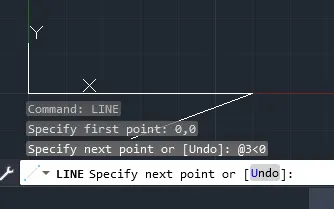
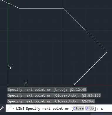
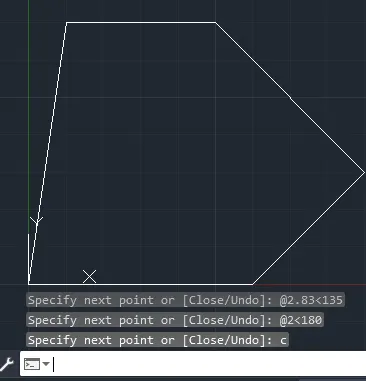
- Now, choose the circle command.
- Provide the center point of the circle as (1.5,1)
- Specify the radius of the circle as 0.6 ( as diameter of the circle is given as 1.2)
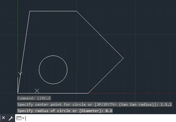
- Again choose circle command.
- Specify the center point of the circle as (1.5,2.5).
- Specify the radius of the circle as 0.4 ( as the diameter of circle is given as 0.8)
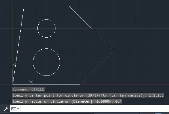
- Now complete the figure by dimensioning it.
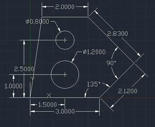
2.
Aim:
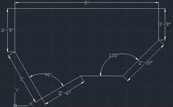
To create the given geometry using AutoCAD tool i.e line using polar coordinate system.
Procedure:
- Initially set the units as Architectural.
- Now set the limits for drawing:
- Specify the lower left corner: (0'0", 0'0")
- Specify the upper right corner: (10'0".6'0")
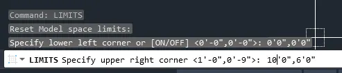
- Now choose the line command:
- Specify the first point: (0'0",5'5")
- Specify the next point: @2'5"<270
- Specify the next point: @3'0"<300 (270+30) (the other angle is 60degrees)
- Specify the next point: @2'6"<30 (Inorder to get included angle 90 degrees the other two angles on either side of included angle is taken as 60degrees and 30 degrees)
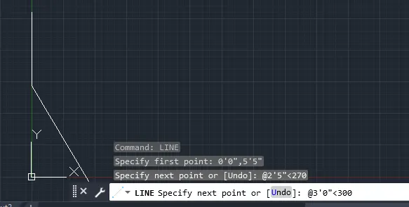
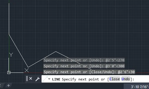
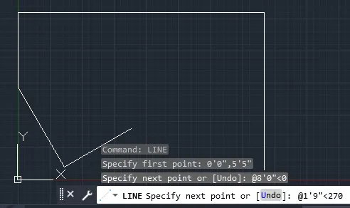
- Now break the line command and again start from the initial point i.e 0'0",5'5". So, choose line command:
- Specify the first point: 0'0",5'5"
- Specify the next point: @8'0"<0
- Specify the next point: @1'9"<270
- Specify the next point: @2'10"<225
- Specify the next point: C
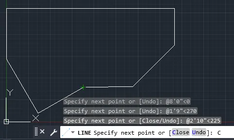
- Now, the figure is completed by dimensioning it.
3.
Aim:
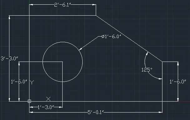
To create the given geometry using AutoCAD tools i.e rectangle, circle, chamfer etc.
Procedure:
- Initially set the units of the drawing as Engineering.
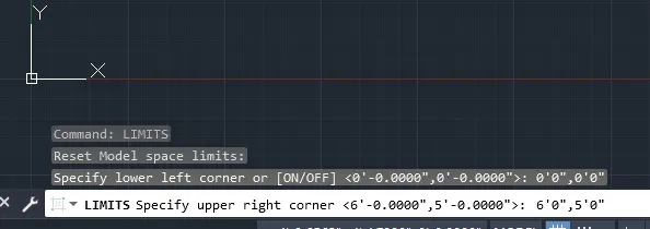
- Then set the limits of the drawing:
- Specify the lower left corner: 0'0",0'0".
- Specify the upper right corner: 6'0",5'0".
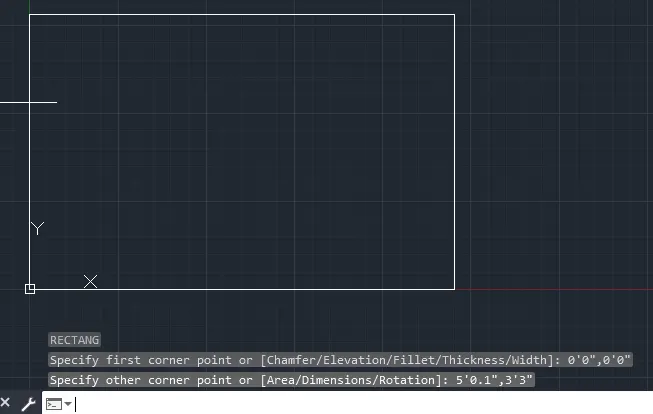
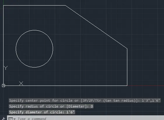
- Now choose the rectangle command:
- Specify the first corner point: (0'0",0'0").
- Specify the next corner point: (5'0.1",3'3")
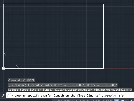
- Now, chamfer the right top corner of the rectangle using chamfer tool:
- Choose angle option in the chamfer command.
- Specify the chamferlength on first line: 1'9" (3'3"-1'6")
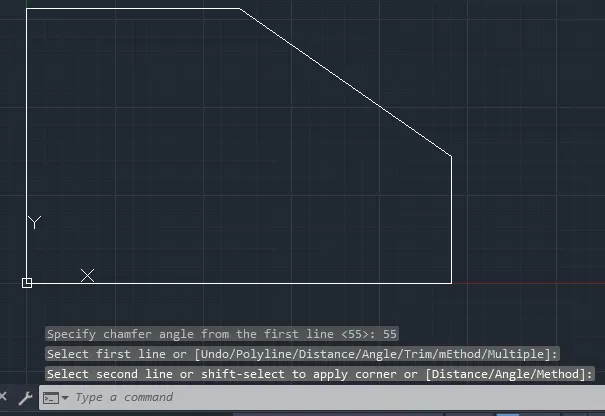
- Specify the chamfer angle from the first line: 55 (180-125)
- Then select the first line to chamfer.
- Now choose circle command:
- Specify the center of the circle: (1'3",1'6")
- Specify the diameter of the circle: 1'6".
- Now complete the figure by dimensioning it.
4.
Aim:
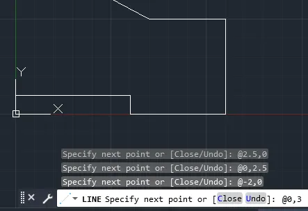
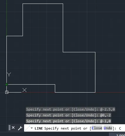
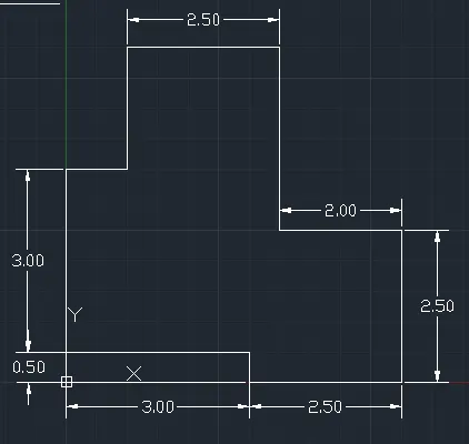
To create the given geometry using the AutoCAD tool i.e polyline using relative rectangular coordinate system.
Procedure:
- Initially set the units of the drawing as Decimal.
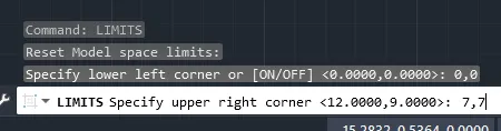
- Then set the limits of the drawing:
- Specify the lower left corner: 0,0.
- Specify the upper right corner: (7,7).
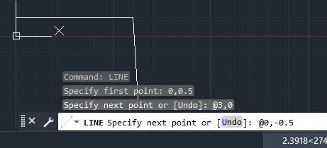
- Now, choose the line command:
- Specify the first point: (0,0.5)
- Specify the next point: @3,0
- Specify the next point: @0,-0.5
-
- Specify the next point: @2.5,0
- Specify the next point: @0,2.5
- Specify the next point: @-2,0
- Specify the next point: @0,3
- Specify the next point: @-2.5,0
- Specify the next point: @0,-2
- Specify the next point: @-1,0
- Specify the next point: C
- Now, complete the figure by dimensioning it.
5.
Aim:
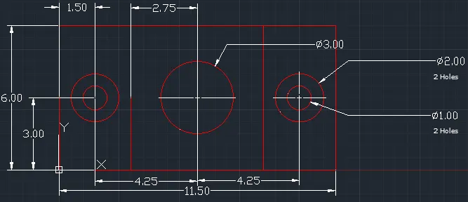
To create the given geometry using AutoCAD tools like rectangle, circle, offset etc.
Procedure:
- Initially set the units of the drawing as Decimal.
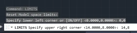
- Then set the limits of the drawing:
- Specify the lower left corner: 0,0.
- Specify the upper right corner: (14,8).
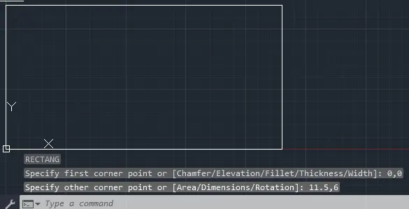
- Now, choose the rectangle command.
- Specify the first corner point: (0,0).
- Specify the next corner point: (11.5,6).
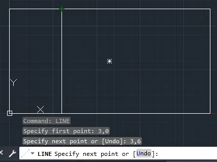
- Now, choose the line command and draw a line at a distance of 3 units from left end.
- Specify the first point of line as (3,0).
- Specify the next point : (3,6).
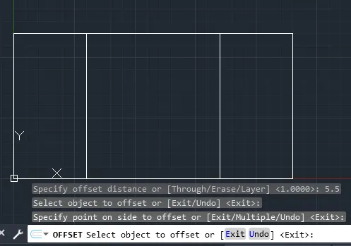
- Then offset this line at a distance of 5.5 units towards right side.
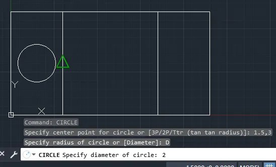
- Now, choose the circle command:
- Specify the center of the circle: (1.5,3).
- Specify the diameter of the circle: 2
- After drawing the circle, offset this circle inwards at a distance of 0.5.
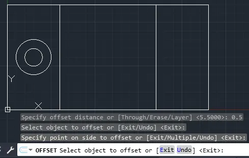
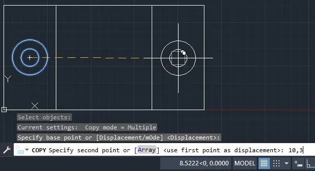
- Now, copy the circles on the left portion to the right portion by keeping the center of the circles as the base point.
- Then specify the second point as (10,3).
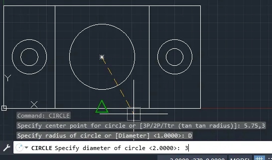
- Again choose the circle command:
- Specify the center point as (5.75,3).
- Specify the diameter of the circle as 3.
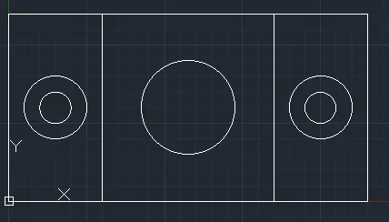
- Complete this figure by dimensioning it.
6.
Aim:
To create geometries using line command and offset command in AutoCAD.
Procedure:
- Initially set the units of the drawing as Decimal.
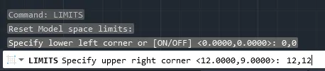
- Then set the limits of the drawing:
- Specify the lower left corner: 0,0.
- Specify the upper right corner: (12,12).
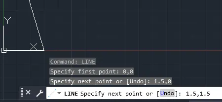
- Now, choose the line option and draw the geometries:
- Specify the first point: (0,0).
- Specify the next point: (1.5,0)
- Specify the next point: (1.5,1.5)
- Specify the next point: (0,1.5)
- Specify the next point: C
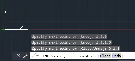
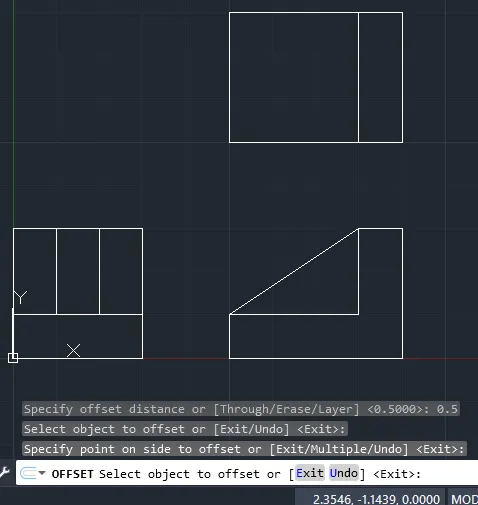
- Now offset the bootom line of the rectangle at an offset distance of 0.5 units inwards.
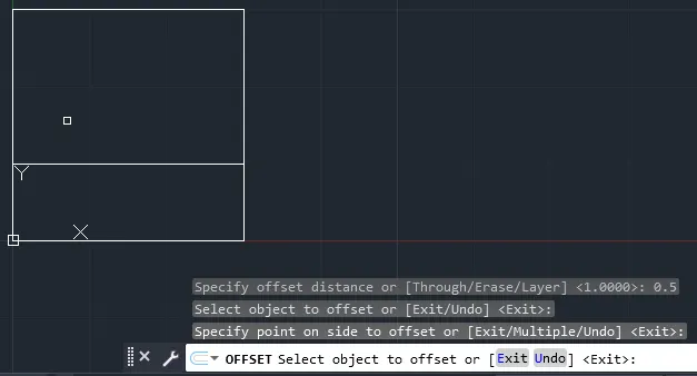
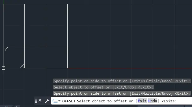
- Also offset the side edge of the rectangle at an offset distance of 0.5units twice inwards.
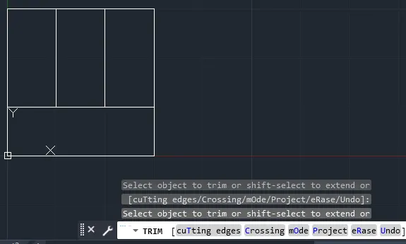
- Then trim off the part of line that extends into the bottom portion.
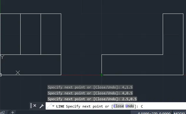
- Now again choose the line command.
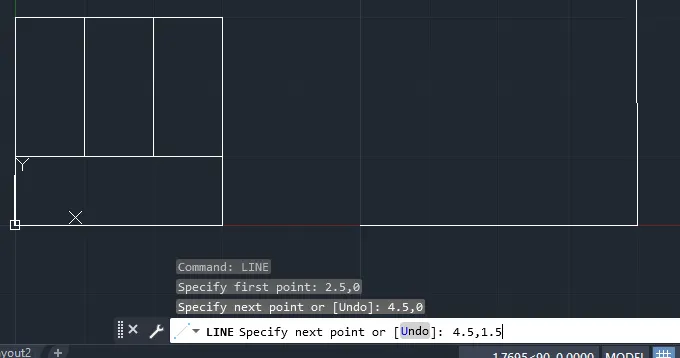
- Specify the first point: (2.5,0)
- Specify the next point: (4.5,0)
- Specify the next point: (4.5,1.5)
- Specify the next point: (4,1.5)
- Specify the next point: (4,0.5)
- Specify the next point: (2.5,0.5)
- Specify the next point: C
- Again choose line command:
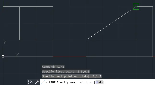
- Specify the first point of line: (2.5,0.5)
- Specify the next point of line: (4,1.5)
- Again choose the line command:
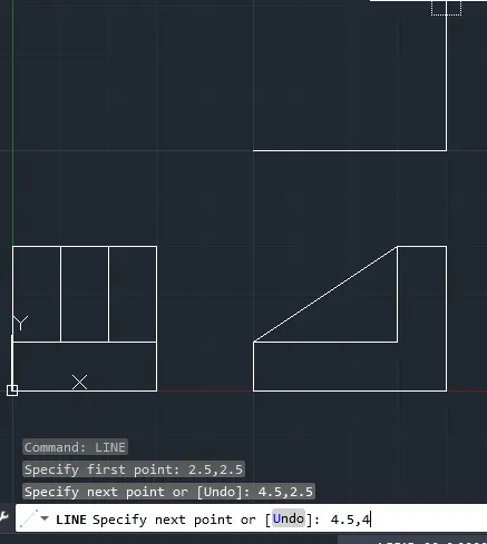
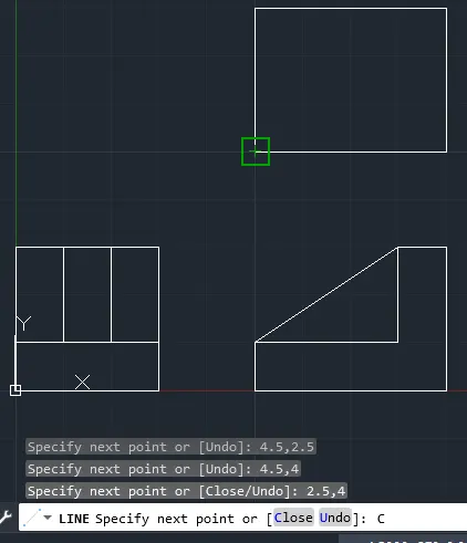
- Specify the first point of line: (2.5,2.5)
- Specify the next point of line: (4.5,2.5)
- Specify the next point of line: (4.5,4)
- Specify the next point of line: (2.5,4)
- Specify the next point of line: C
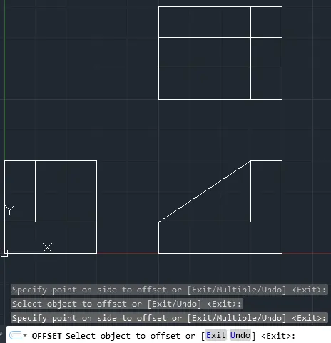
- Now offset the right edge of the rectangle at an offset distance of 0.5units inwards.
- Similarly offset the top edge of the rectangle at an offset ditsance of 0.5 units inwards twice.
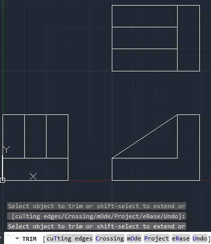
- Now, trim off the portion of the line that extend into the right portion of rectangle.
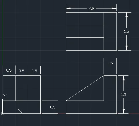
- Complete the figure by dimensioning it.
7.
Aim:
To create the geometry using line, rectangle, circle, arc, fillet etc in AutoCAD.
Procedure:
- Initially set the units of the drawing as Decimal.
- Then set the limits of the drawing:
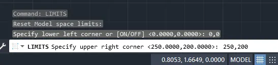
- Specify the lower left corner: 0,0.
- Specify the upper right corner: (250,200).
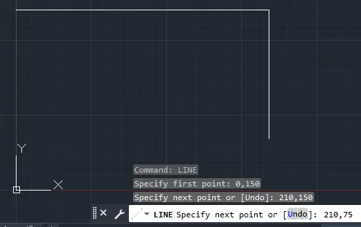
- Now choose line command:
- Specify the first point of line: (0,150)
- Specify the next point of line: (210,150)
- Specify the next point of line: (210,75)
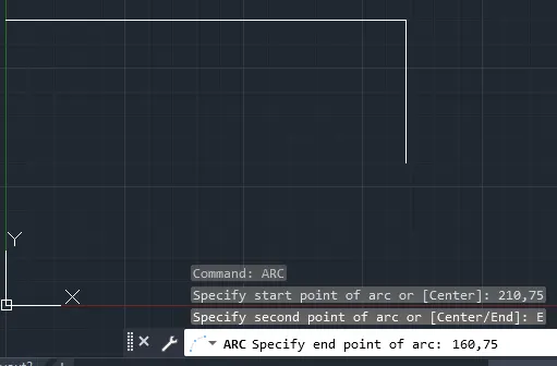
- Now, choose arc command:
- Specify the start point of arc: (210,75)
- Choose end option in the arc command.
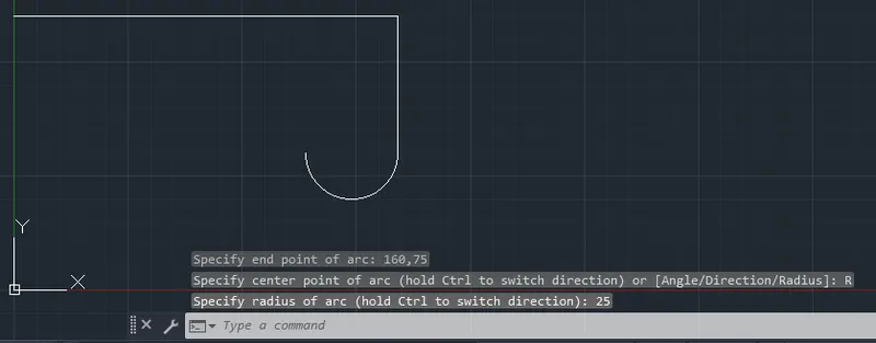
- Specify the end point of arc: (160,75)
- Inorder to switch the direction of arc hold ctrl.
- Specify the radius of the arc: 25
- Now again choose line command :
- Specify the first point of line: (160,75)
- Specify the next point of line: (160,90)
- Specify the next point of line: (70,90)
- Specify the next point of line: (70,50)
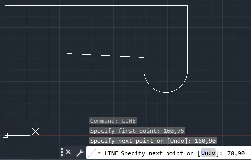
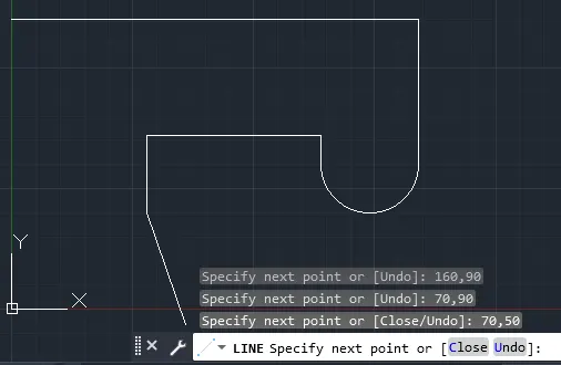
- Now, choose arc command:
- Specify the start point of arc: (70,50)
- Choose end option in the arc command.
- Specify the end point of arc: (0,50)
- Inorder to switch the direction of arc hold ctrl.
- Specify the radius of the arc: 35
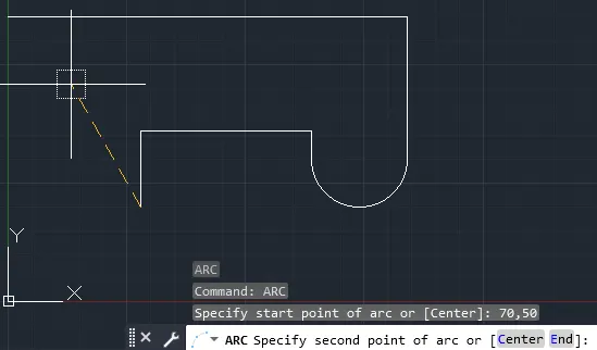
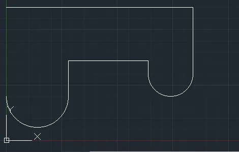
- Now, close the figure with the command C.
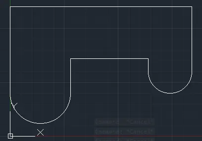
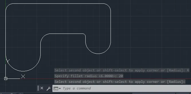
- Now, we have to fillet the corners of the figure using the command fillet:
- Select the first object to fillet.
- Then choose the radius option and specify the radius as 15units.
- Finally select the second object.
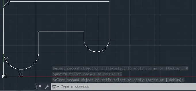
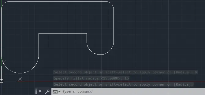
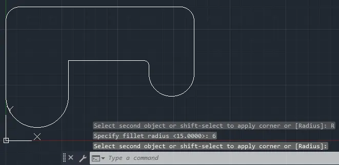
- Similarly, fillet the other corners of radius 15, 6 and 20 units respectively.
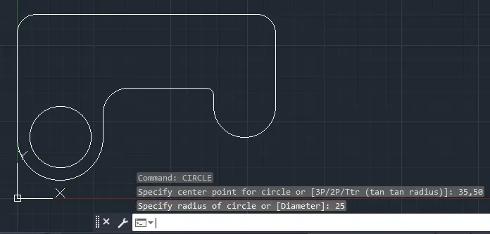
- Choose the circle command:
- Specify the center of the circle: (35,50)
- Specify the radius of the circle: 25
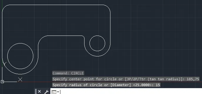
- Again choose circle command:
- Specify the center of the circle: (185,75)
- Specify the radius of the circle: 15
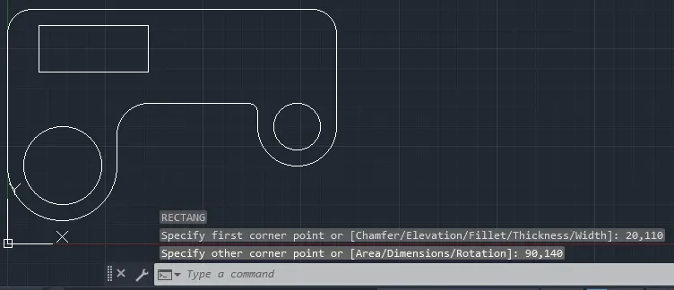
- Choose rectangle command:
- Specify the first corner point: (20,110)
- Specify the other corner point: (90,140)
- Now copy this rectangle by choosing left bottom corner as base point to the point having coordinates (120,110).
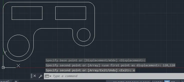
- Now complete the figure by dimensioning it.
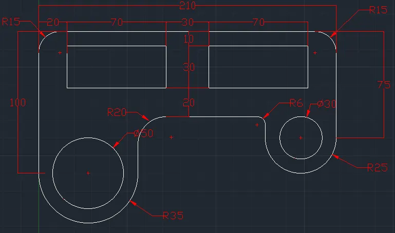
8.
Aim:
To create geometries using circle, line, offset etc in AutoCAD software.
Procedure:
- Initially set the units of the drawing as Decimal.
- Then set the limits of the drawing:
- Specify the lower left corner: 0,0.
- Specify the upper right corner: (20,20).
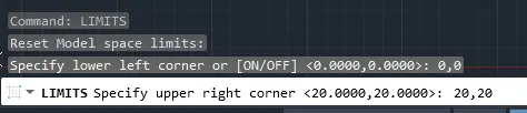
- Choose the circle command:
- Specify the center point of circle: (7,7)
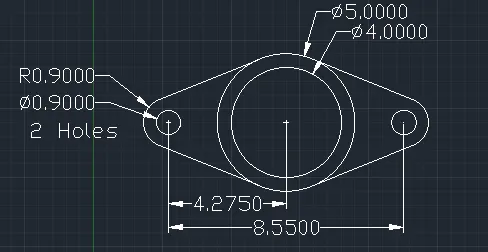
- Specify the diameter of the circle: 5
- After this, offset the circle at an offset distance of 0.5units inwards.
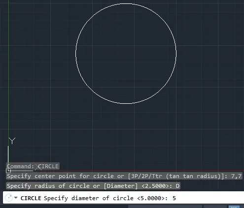
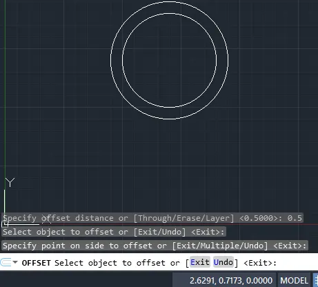
- Now, choose line command and draw a center line for the circle both verticall and horizontally.
- Then offset this line on either side of the circleat an offset distance of 4.275 units.
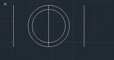

- Offset the central horizontal line on eithe side at an offset distance of 0.9 units and the trim off the unwanted portion.
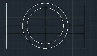
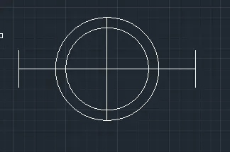
- Now, draw tangents to the circle from all four points on extreme ends.
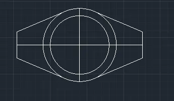
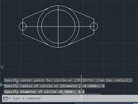
- Now, choose the circle command and draw two circles having diameter 0.9units on either side by keeping the intersection point as the center.
- Now, choose arc option:
- Specify the start point of arc: (2.72,6.1)
- Choose end option in the arc command.
- Specify the end point of arc: (2.72,7.9)
- Inorder to switch the direction of arc hold ctrl.
- Specify the radius of the arc: 0.9
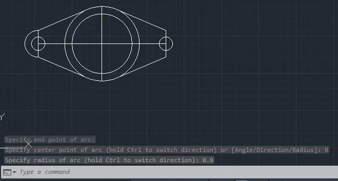
- Similarly draw an arc on the right side.
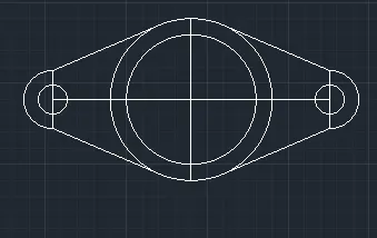
- Now, using line option draw a tangent to the arc on either side and then trim off the excess lines.
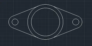
- Complete the figure by dimensioning it.
9.
Aim:
To create the given geometry using circle
Procedure:
- Initially set the units of the drawing as Decimal.
- Then set the limits of the drawing:
- Specify the lower left corner: 0'0",0'0".
- Specify the upper right corner: (100'0",100'0").

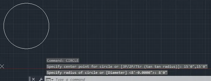
- Choose the circle command:
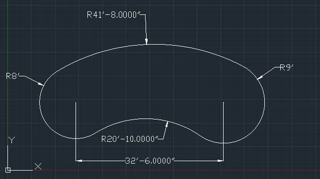
- Specify the center of the circle: (15'0",15'0")
- Specify the radius of the circle: 8'0".
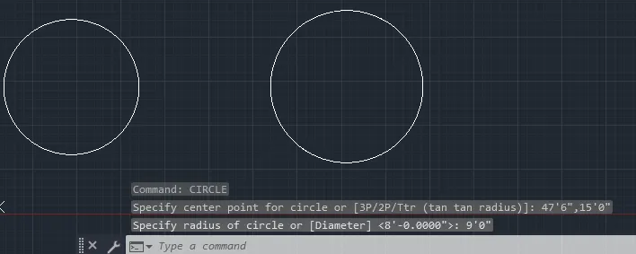
- Now, draw another circle whose center is at a distance of 32'6" from the center of this circle.
- Specify the center of the circle: (47'6",15'0")
- Specify the radius of the circle: 9'
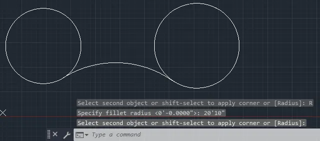
- Now, choose the fillet option and provide a fillet of radius 20'10" at the bottom of the two circles.
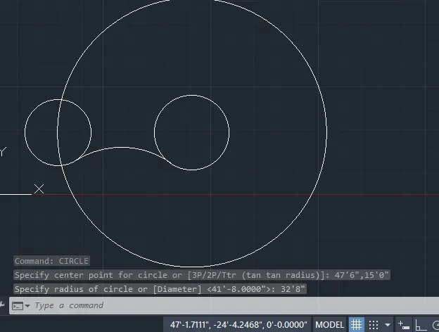
- Now to draw the upper curve in the figure, use circle command:
- Specify the center of the circle: (47'6",15'0")
- Specify the radius of the circle: 32'8"
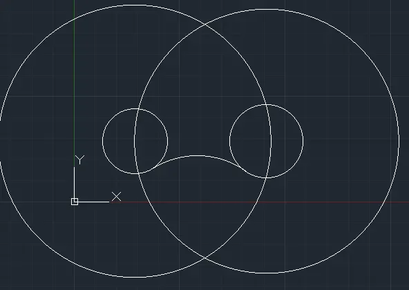
- Then draw another circle:
- Specify the center of the circle: (15'0",15'0")
- Specify the radius of the circle: 33'8"
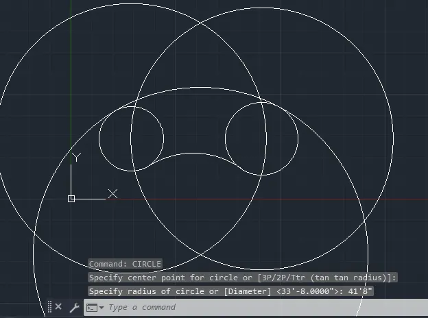
- Now at the point of intersection of the two circle at the bottom is kept as the centre of another circle having radius 41'8".
- After this trim off the unwanted portion.
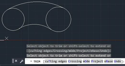
- Now complete the figure by dimensioning it.
10.
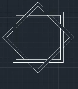
Aim:
To create a geometry using the rectangle, offset , rotate aand trim tool in AutoCAD.
Procedure:
- Initially set the units of the drawing as Decimal.
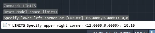
- Then set the limits of the drawing:
- Specify the lower left corner: 0,0.
- Specify the upper right corner: (10,10).
- Now, choosebrectangle command:
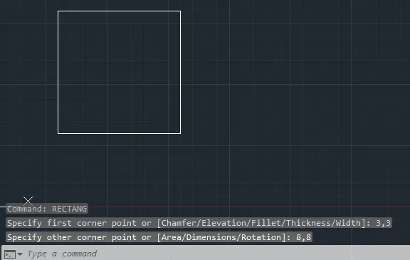
- Specify the first corner of rectangle: (3,3)
- Specify the other corner of rectangle: (8,8)
- Then, offset this rectangle inwards at an offset distance of 0.3 units.
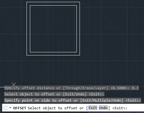
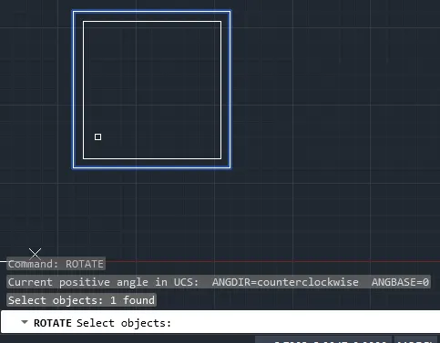
- Now, rotate the entire figure with copy option at a rotation angle of 45 degrees.
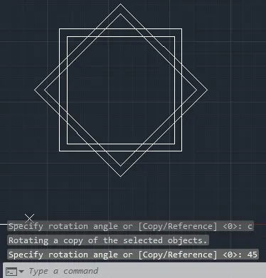
- Now trim off the overlapping portion.
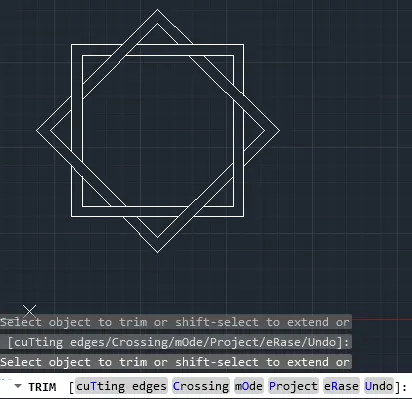
- Hence, the figure is completed.
11.
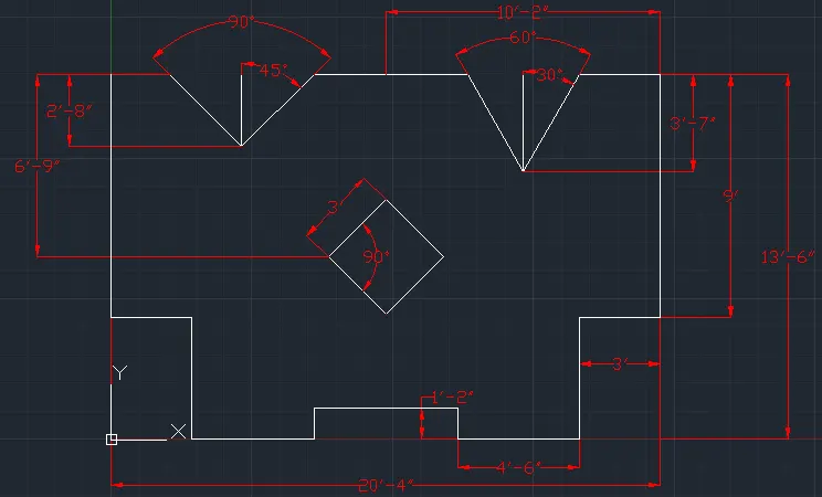
Aim:
To create given geometry using line, rectangle ,rotate tool in AutoCAD using relative polar coordinate system.
Procedure:
- Initially set the units of the drawing as Architectural.
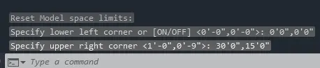
- Then set the limits of the drawing:
- Specify the lower left corner: 0'0",0'0".
- Specify the upper right corner: (30'0",15'0").
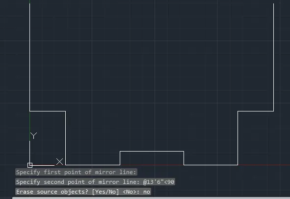
- Choose line command:
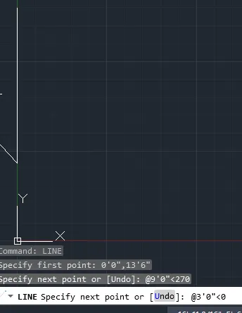
- Specify the first point: (0'0",13'6")
- Specify the next point: @9'0"<270
- Specify the next point: @3'0"<0
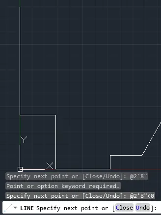
- Specify the next point: @4'6"<270
- Specify the next point: @4'6"<0
- Specify the next point: @1'2"<90
- Specify the next point: @2'8"<0
- Now, mirror this figure to obtain this exact geometry on the right side.
- Again choose line command to complete the figure:
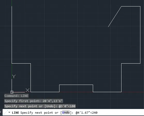
- Specify the first point: 20'4",13'6"
- Specify the next point: @3'0"<180
- Specify the next point: @4'1.67"<240
- Specify the next point: @4'1.67"<120
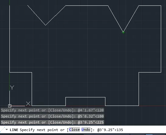
- Specify the next point: @5'8.32"<180
- Specify the next point: @3'9.25"<225
- Specify the next point: @3'9.25"<135
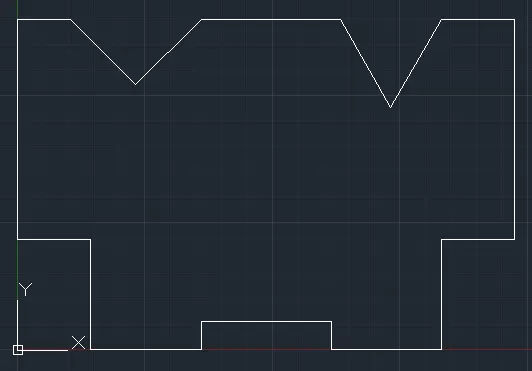
- Specify the next point: C
- Now choose rectangle command:
- Specify the first corner point: (8'8",5'3")
- Specify the other corner point: (11'8",8'3")
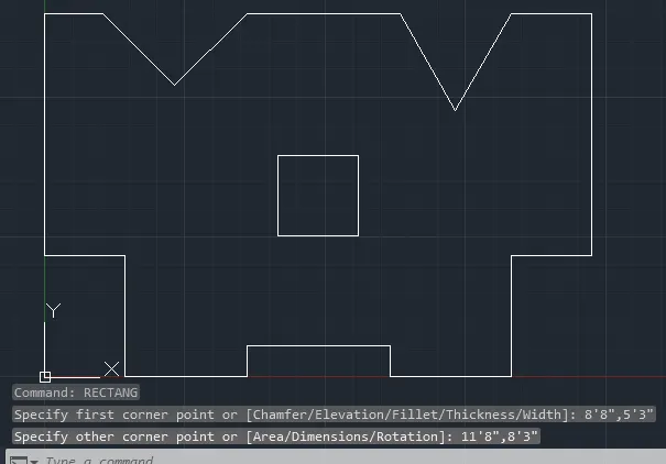
- Now, rotate this rectangle at a rotation angle of 45 degrees and then complete the figure by dimensioning it.
Result:
The given geometries have been created using different tools in AutoCAD software like line, rectangle, circle, offset, chamfer, fillet, offset, trim etc. The completed drawings are shown below:
1.
2.
3.
4.
5.
6.
7.
8.
9.
10.
11.