Creating a Residence Layout, Seating plan, Toilet and Utility room plan using AutoCad
Introduction:
Inorder to create a residence layout, seating plan etc in AutoCAD software various tools that will be helpful are construction line(XLINE), Offset, trim, fillet, circle, arc, layer etc.
The detailed explanation for each tools are as follows:
- Construction line:
- Command used: XLINE . This tool can also be evoked from ribbon.
- These are temporary linework entities that can be used as references when creating and positioning other objects or lineworks.
- These are either circles or straight lines that extend to infinity in both directions.
- While drawing a residential plan construction lines are very important to draw the outline of the plan.
- Offset:
- Command used: OFFSET, it can also be evoked from ribbon, toolbar.
- There are different options available in offset command:
- Through option: offsetting is done without providing the offset distance.
- Erase option: This is an option to confirm the erasing of the source object after offsetting.
- Layer option: It determines whether the offset objects are created on the current layer or on the layer of the source object.
- Trim:
- Command used: TRIM and can also be evoked from ribbon and toolbar.
- This command in AutoCAD is used to remove the objects which meet the edges of other objects or to remove extra lines or extra parts of an object.
- Different options available are fence, crossing, erase, undo, project(for 3D objects), edge.
- Fillet:
- Command used: FILLET and can also be evoked from ribbon and toolbar.
- In residential plan drawing fillet is very useful in creating corner walls. This can be done by providing the radius of fillet as 0.
- Circle:
- Command used: CIRCLE and is also evoked from ribbon, toolbar, menubar and tool pallettes.
- Different options available in circle tool: Center and radius; center and diameter; two point; three point; tangent, tangent, radius; tangent,tangent,tangent.
- Arc:
- Command used: ARC or A
- To create an arc there are different combination which can be used like center, endpoint, start point, radius, angle, chord length and direction values.
- Arcs are drawn in counter clockwise direction by default. Hold down the ctrl key as you drag to draw in a clockwise direction.
- Layers:
- Command used: LA.
- It is a concept that allows to group down geometry in distinct and separate categories according to similar features or common theme.
- It allows to exercise control over drawing y ong other things, applyng properties to the layers such as assigning colours and linetypes.
- It is also possible to manipulate each individual layer, making it visible or invisible for clarity as well as being able to lock them to prevent editing.
1.
Aim:
To sketch the layout of residence using the tools in AutoCAD software.
Procedure:
- Initially set the units of drawing as Architectural.
- Now set the limits of drawing:
- Specify the lower left corner : (0'0",0'0")
- Specify the upper right corner: (75'0",75'0")
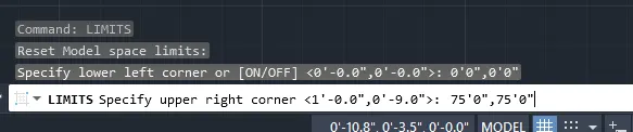
- Now, use construction line to draw the walls of the residence.
- Command used is XLINE.
- Choose vertical option to draw the construction line vertically.
- After this, again draw a construction line horizontally by choosing option horizontal.

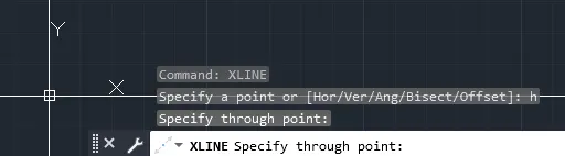
- Now, offset these line to obtain different rooms according to the sketch provided.
- External wall thickness is 9" hence initially offset these lines to obtain walls both horizontally and vertically. Hence, corner of the wall is obtained.
- Internal wall thickness is 4.5".
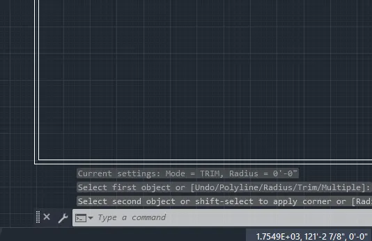
- Now these horizontal lines are offsetted according to given plan.
- Now the vertical lines are offsetted according to the given plan.
- After this, openings are created by trim option and also the unwanted portion is trimmed off.
- Finally the outline of the residence layout is obtained.
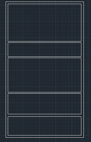
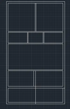
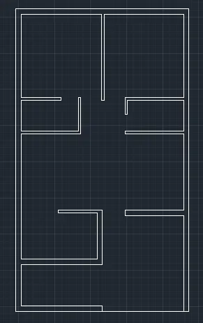
- Now using line tool and offset tool draw the staircase, kitchen slab, cupboard.
- Then, using circle and line tool draw the doors.
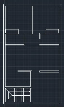
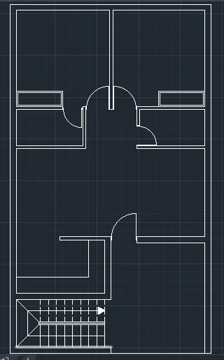
- Now complete the figure by dimensioning it.
- After dimensioning and naming it is then assigned to different layers like exterior walls, interior walls, slabs, dimesions texts etc. by which it can be easily seected.
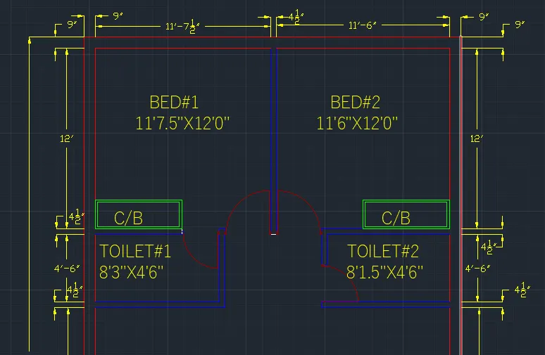
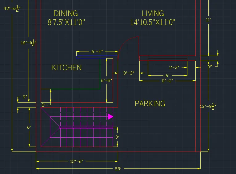
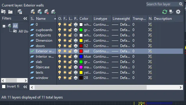
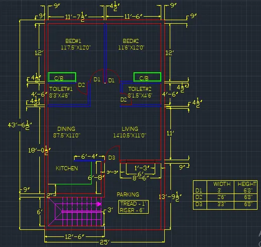
- Now the complete figure is given below:
2.
Aim:
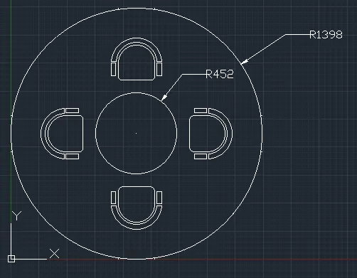
To create the sketch of a seating plan for an outdoor canopy.
Procedure:
- Initially set the units of drawing as Decimal(mm).
- Now set the limits of drawing:
- Specify the lower left corner : (0,0)
- Specify the upper right corner: (5000,5000)

- Now, choose circle command:
- Specify the center point of the circle: (1400,1400)
- Specify the radius of the circle: 1398
- Again choose circle command:
- Specify the center point of the circle: (1400,1400)
- Specify the radius of the circle: 452
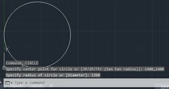
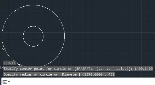
- Now, draw two construction line i.e horizontal and vertical passing through the center of the circle.
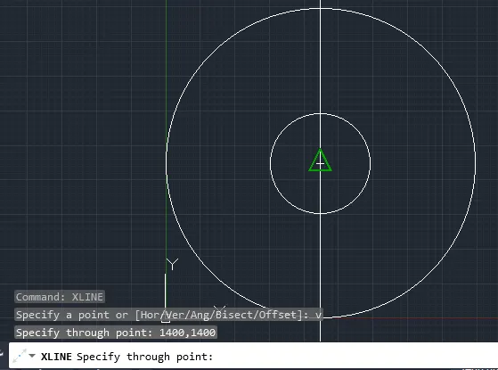
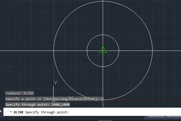
- Trim off the portion extending out of the bigger circle.
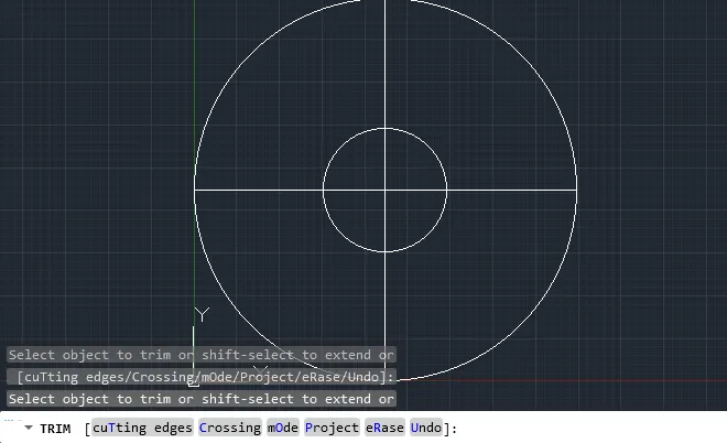
- Now using the offset option, the center line is offsetted at a distance of 200mm on either side to obtain a rectangular portion of the seat on all four sides.
- Then trim off the unwanted portion.
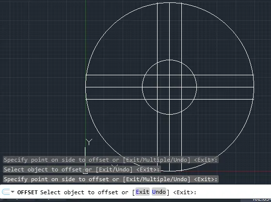
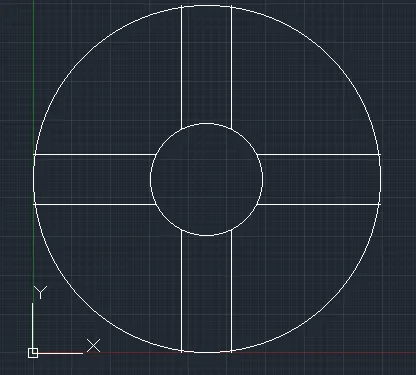
- Using the line command sketch one side of the seat. Later on the corners of the edge towards the center are then filletted with a fillet radius of 50mm.
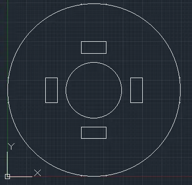
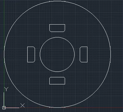
- Now choose the arc option and draw an arc on the flat edge of the reactangle for all the four seats.
- The arc is drawn using start,end and direction option.
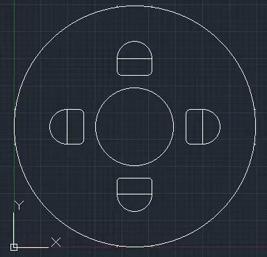
- Now trim off the line inside the seat portion.
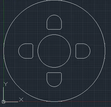
- After this, use the offset option to offset the arc and line portion.
- Offset distance taken is 30mm for first offset and then 50mm for next offset.
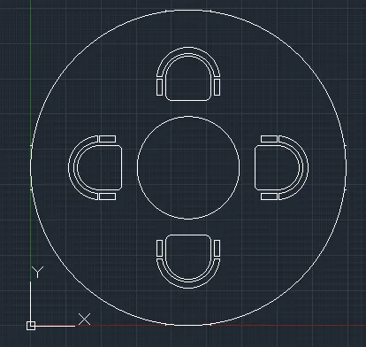
- This figure is then completed by providing the dimensions.
3.
Aim:
To sketch the part plan for the toilets and utilities room.
Procedures:
- Initially set the units of drawing as Decimal(mm).
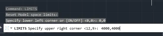
- Now set the limits of drawing:
- Specify the lower left corner : (0,0)
- Specify the upper right corner: (4000,4000).
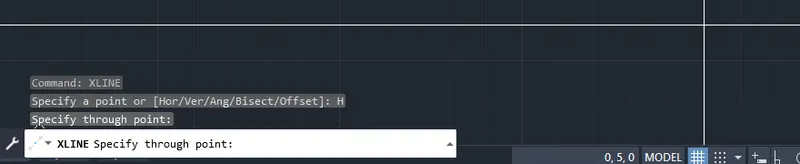
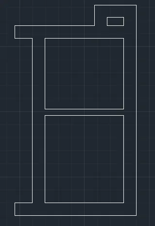
- Now,use the construction line to draw the outline of given plan. The command used is XLINE.
- Draw construction line vertically and horizontally to obtain the right corner.
- Offset the these line at an offset distance of 300mm which is the thickness of exterior walls and for the interior walls offset distance is taken as 150mm.

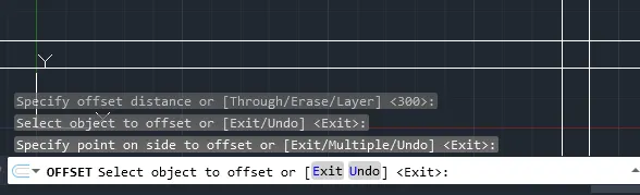
- The complete outline of the plan is created by using the tools offset, trim and extend.
- After this, openings are created by trim option.
- Then the doors and windows are creates using line option, circle etc.
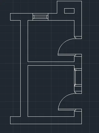
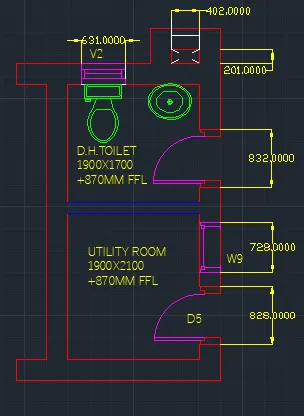
- Now include water closet and wash basin in toilet.
- Then complete the figure by dimensioning it.
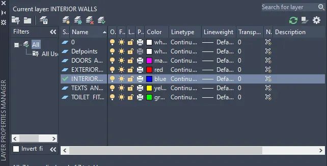
- After dimensioning, different components are assigned to different layers like exterior walls, interior walls etc.
Result:
Using the tools in AutoCAD, the sketches completed are as follows:
1. Residence plan:
Layer information:
2. Outdoor seating with canopy:
3. Part plan for toilers and utilities room:
Layers information: