Drafting of various geometries using Chamfer, Fillet tool in AutoCad
AIM:
To draw the attchments in the PPt as per dimensions using Chamfer and Fillet tool in AutoCAD.
INTRODUCTION:
The AutoCAD software is mostly used by the engineers such Civil, Mechanical and Electrical. The drawings or planning of an object or the component which are predetermined by using AutoCAD. It was the best tool in early days for engineers. The following are some of the drawings to learn the autocad using the tools chamfer and fillet.
PROCEDURE:
Initially open the AutoCAD software and set the units using the command UN and set the units as Metre and precision as 0.00 . It will show Rescale Objects dialogue bar. Click on the rescale model and paper objects.
Then, set the limits using command LIM and set the limits lower left cornor as <0,0> and the upper right cornor as <50,50> to draw what they asked.
After that, Type DS and set the snap as 0.001 and the grid as 0.1 for the better ease to work. Also Press F8 to turn on ortho for perfect striaght lines.
Then choose line command by typing L and set the coordonates as {1,1} and do further.
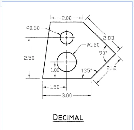
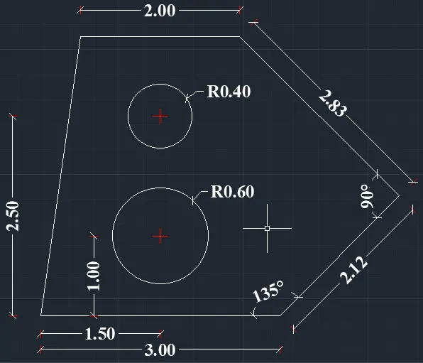
DRAWING 1:
Drag to right and type 3 and press enter.
Drag to right and type 2.12 and press tab and type 45 and press enter.
Drag to top and type 2.83 and press tab and type 135 and press enter.
Drag to left and type 2 and press enter.
close the object.
Type XL and press enter and type V and press enter. A construction line will show, then place the line at the starting point or at<1,1> and press enter. Then select the construction line and type offset and then drag the cursor to right and type 1.5 and enter.
Same way, Type XL and press enter and type H and press enter. A construction line will show, then place the line at the starting point or at<1,1> and press enter. Then select the construction line and type offset and then drag the cursor to right and type 1 and enter. again select the same Xline and type 2.5 and enter.
type C, press enter and place the point on the first merging point from bottom and drag then type 0.6(radius), press enter. A circle will be created in the required place at 1.2ϕ
type C, press enter and place the point on the second merging point from bottom and drag then type 0.4(radius), press enter. A circle will be created in the required place at 0.8ϕ
Erase the Xlines in the drawing and the required dimensions, the drawing is plotted using Autocad.
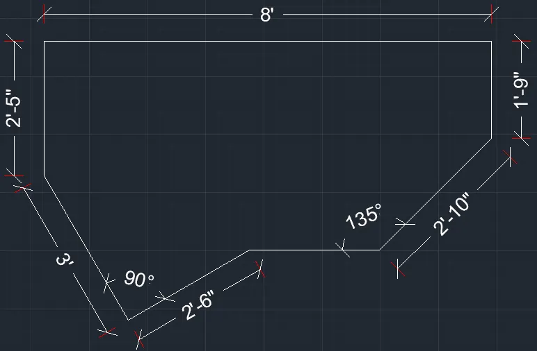
DRAWING 2:
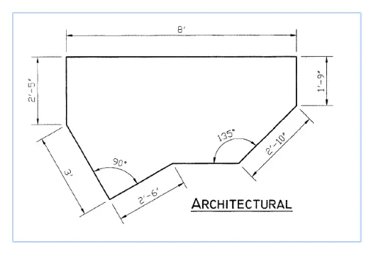
1.Select architectural and polar tracking for angles 15,30,45,60 and so on.
2.Command line: Draw a horizontal line and draw 2'6'' line at 225 degrees, 3' line perpendicular to it, 2'5'' vertical line and 8' horizontal line, 1'9'' vertical line and 2'10'' @225 degrees and close.
DRAWING 3:
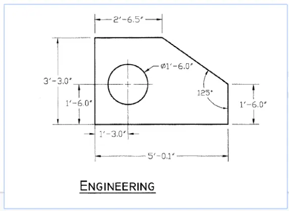
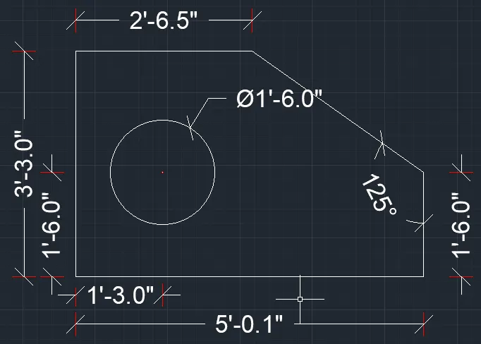
1.Open new file and set engineering and precision to 0'-0.0"
2.Command line: 2'-6.5" in -ve X-axis, 3-3" in -ve Y-axis, 5-0.1" in +ve X-axis, 1-6.0" in +ve Y-axis and close.
3.Command offset: offset 3'-3" line at a distanceof 1'-3.0" and 5'-0.1" at a distance of 1'-6.0"
4.Command circle: draw a circle of diameter of 1'-6.0" from the centre of offsetted lines.
5.Command erase: Erase the offsets.
DRAWING 4:
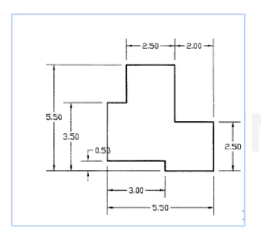
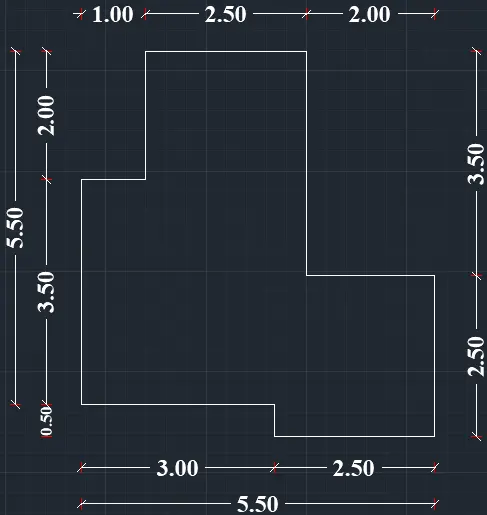
1.New page and select decimals with precision 0.00 while keeping ortho on.
2.Command line:Draw 3.00m line in +ve X axis
3.0.50 In -ve Y axis, 2.50m in +ve X axis, 2.50m in +ve Y axis, 2.00m in -ve X axis, 3.00m in +ve Y axis, 2.50m in -ve X axis, 2.00m in -ve Y axis, 3.00m in -ve Y axis and close.
DRAWING 5:
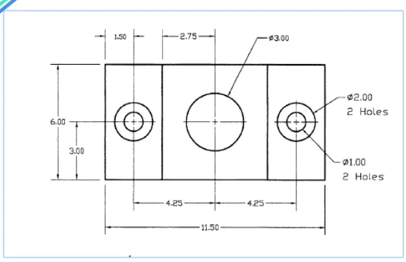
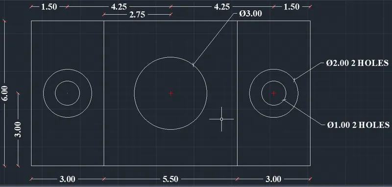
1.New page select decimal and precision 0.00 while keeping ortho on.
2.Command line: 6.00m vertical. 11.50m horizontal and 6.00m vertical and 11.50m horizontal.
3.In object snap setting keep midpoint, centre, intersection and geometric centre on.
4.Command Circle: Draw circle at the centre with diameter 3.00m
5.Command offset: offset 6.00m line at a distance of 3.00m on both sides and offset the 11.50m line at adistance of 3.00m.
6.Command circle: Draw concentric circles at the intersection of the offsetted line of diameter 1.00m and 2.00m on both sides.
7.Command erase: Erase the offsets.
DRAWING 6:
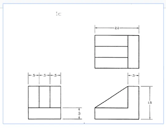
1.New page select decimal with precision 0.0.
2.Command line:1.Sm horizontal and 1.5m vertical on both sides.
3.Command offset offset 1.5m line to 0.5m.
4.Command divide: Divide 1.5m line into 3 segments.
5.Command line-: Join the divided lines.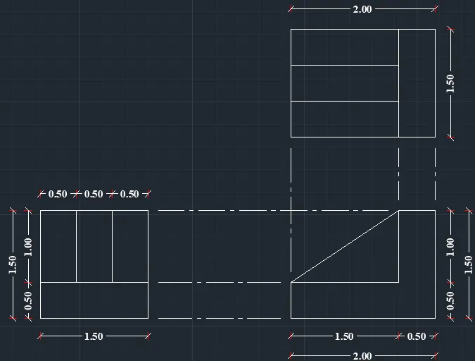
6.In object snap setting keep the Extension On
7.C0mrmand line: Draw 2.0m line and 1.5m line and O.5m horizontal on top and ln vertical and 1.5m horizontal and O.5m vertical and join the slant line.
8.Command line:2.0m horizontal and 1.5m vertical on both sides.
9.Command offset: offset 1.5m line to O.5m.
10.Command divide: Divide 1.5m line into 3 segments.
11.Command line: Join the divided lines.
DRAWING 7:
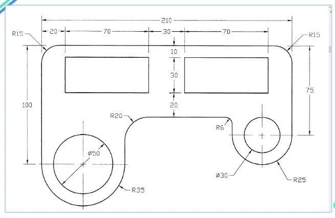
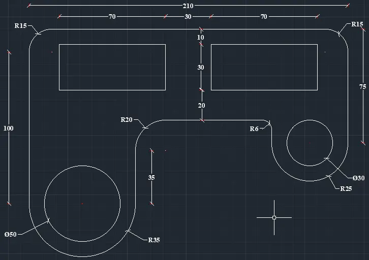
1.New page and set decimal and precision to 0
2.Command line: Drawing 210m horizontal line and 100m vertical line on left side and 75m vertical line on right side, since arc has radius of 35m drawing a line of 70m on left side and has a radius of 25m drawing a line of 5Om on right side.
3.Command Arc: From start, end and radius draw an arc of radius 35m on right side and an arc of radius 25m on leh side.
4.Command Circle: From midpoint of 70m line on left side draw a cirle of diameter of 5Om and 30m on right side.
5.Command offset Offset 210m line at a distance of 60m.
6.Command fillet:Filleting to radius 15m on top right and left and radius of 20m on inner left and radius of 6m on inner right.
7.Command offset:offsetting 210m line to !Om and 100m and 75m line to 20m.
8.Command rectangle·:70m length and width of 30m from off setted line on both sides.
9.Command erase: Erasing the otfsetted line and unwanted lines.
DRAWING 8:
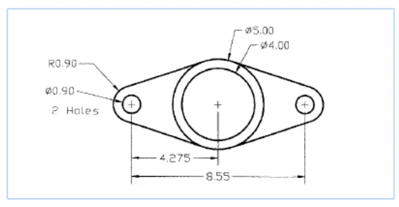
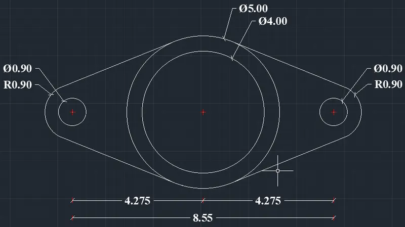
1.New page set decimal and precision to 0.00
2.Command cirde:Draw concentric circles of diameter 5.00m and 4.00m
3.Command line: From the centre point of circle draw 4.275m line on both sides.
4.Command circle: Drawing a circle of diameter 0.90m on both sides.
5.Command arc: from start, end and radius draw an arc of radius 0. 90 on both sides
6.Command line: Join the lines to the arc.
DRAWING 9:
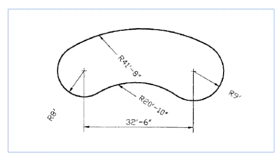
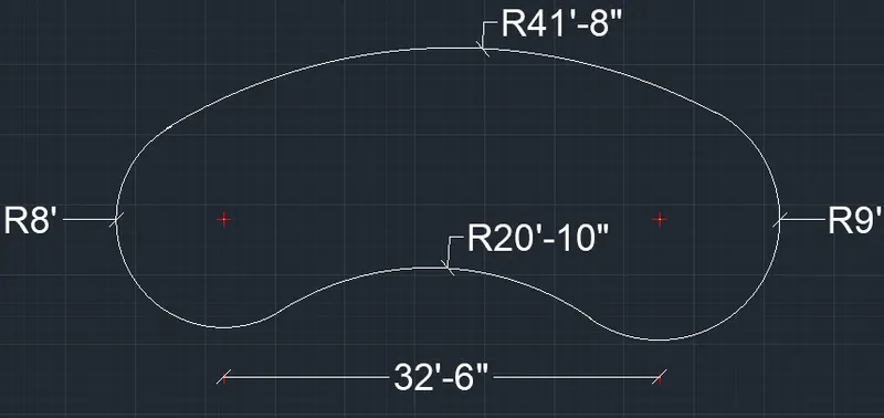
1.New page and set Engineering and precision to 0'-0"
2.Command Line: Draw a 32'-6'' horizontal line.
3.Command circle:Draw a circle of radius 8' on left side of line and radius of 9' on right side of line.
4.Command Arc: From start, end and radius drawing a arc of 41'-8" on top and 20'10" on bottom.
5.Command trim: trim the unwanted line and curves.
DRAWING 10:
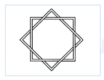
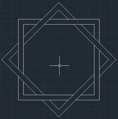
1.Command rectangle: Draw a rectangte of same length and same width of one smaller size and another slightly bigger one from common centre.
2.Command Rotate: Rotating the drawn squares by 45 degree keeping the copy
3.Command trim:Trim the crossing lines according to the figure.
DRAWING 11:
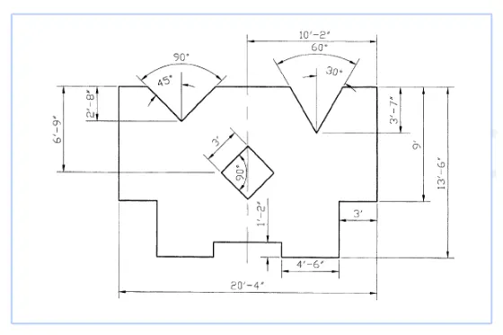
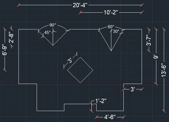
1.New page and set engineering and precision 0'0"
2.Command line: Draw 10' -2" horizontal line, 9' vertical line, 3' horizontal line,4'-6" vertical and horizontal line and 1'-2" vertical line.
3.Command mirror: Mirror the above lines at centre axis.
4.Command offset: offset the 20'-4" to a distance of 6'-9" arnd 13'-6'' to a distance of 10'-2".
5.Command Rectangle: Draw a rectangle of length and width 3' from the centre point of off setted line.
6.Command Move: moving the centre of rectangle to the centre of offsetted line.
7.Command rotate: Rotating the Rectangle by 45 degrees
8.Command offset: Offsetting 20'-4" to a distance of 2'-8" with polar tracking on draw an angle of 90 degrees. Offset 20'-4" to a distance of 3'-7' with polar tracking on draw an angle of 60 degrees.
9.Command erase: Erase the unwanted lines.
RESULT:
The given drawings have been drawn using autocad. The above drawings are a little complicated to understand and after when I drew them in autocad it will give me some confidence that I'm somewhat improved in AutoCAD.