Creating a Residence Layout, Seating plan, Toilet and Utility room plan using AutoCad
QUESTION : Creating a Residence Layout, Seating plan, Toilet and Utility room plan using AutoCad
ANSWER:
AIM : - Creating a Residence Layout, Seating plan, Toilet and Utility room plan using AutoCad
INTRODUCTION:-
AUTOCAD: AutoCAD is a commmericial computer aided drawing CAD and drafting software application .DEveloped and marketed by Autodesk . AutoCAD was first released in DEcember 1982 as a desktop app running on microcomputers with internal graphics controllers.
OBJECTIVE : the objective of this Projecct is to practice the autocad commands and draw advanced drawings like layout plan, Seating plan , Toilet and utility plan using AutoCAD software.
PROCEDURE:
DRAWING NO. -1
FOR START ANY DRAWING FIRST OF ALL WE HAVE TO DO SOME SETTINGS ACCORDING THE DRAWING -
SETTINGS - OPEN AUTOCAD
- SET DEFAULT SETTINGS - IMPERIAL UNIT (feet and inches)
- SELECT A TEMPLATE - ACCORDING TO DRAWINGS
- SELECT A WIZAED - ADVANCED SETUP
- UNITS - ENGINEERING , PRECISION -0.00
- ANGLE - DECIMAL DEGREES
- ANGLE MEASURE - ACCORDING TO PLAN
- ANGLE DIRECTION - COUNTER CLOCKWISE
- AREA - ACCORDING TO PLAN
After this enter "D" for dimetion unit and set primary unit Engineering set precision 0.00
MODES -
- GRID ON BY F7 'CONTROL+G'
- USE ORTHO MODE FOR STRAIGHT 90 DEGREE ACCRDING NEED(F8)
- ON POLAR TRACKING (F10) SET ANGLE (15,30,45)
- OBJET SNAP TRACKING (F11)
- OBJECT SNAP (F3)
- TRANPARANCY ON WHEN YOU NEED
SOME OTHER DATA
- OUTER WALL THICKNSS 0'-9.0"
- INTERNAL WALL THICKNESS 0'-4.5"
- DI DOOR - WIDTH 3'
- D2 DOOR - WIDTH 2'-6"
- D3 DOOR - WIDTH 3'-3"
- HEIGHT OF ALL DOOR 6''8"
TO DRAW THE LAYOUT PLAN WE FOLLOW THE FOLLOWING STEPS : -
STEP -1
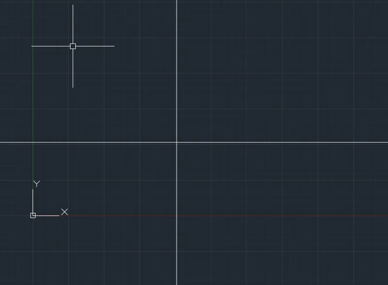
- Take onstruction line by enter command XL or from ribbon.
- Put it vertically and horizontally according to step one drawings.
STEP -2
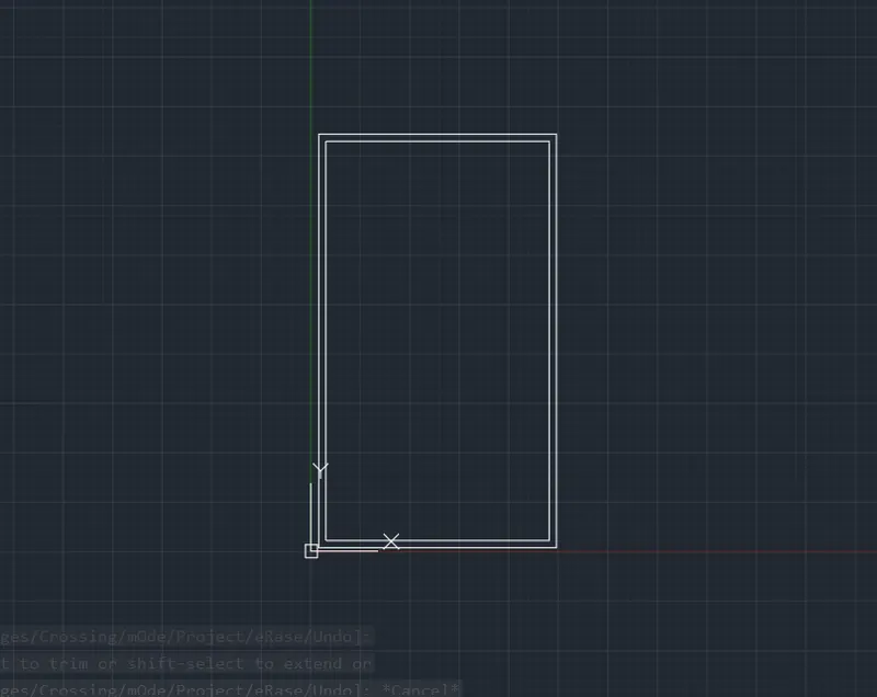
- Take offset 43'-6.5" from horizontal line
- Again take offset 0.9" from upper line to downward for outer wall
- Take offset 25' from vertical line forward (X) Direction
- wall offset 0.9"from internal side.
- Trim unwanted line by using Trim command.
STEP -3
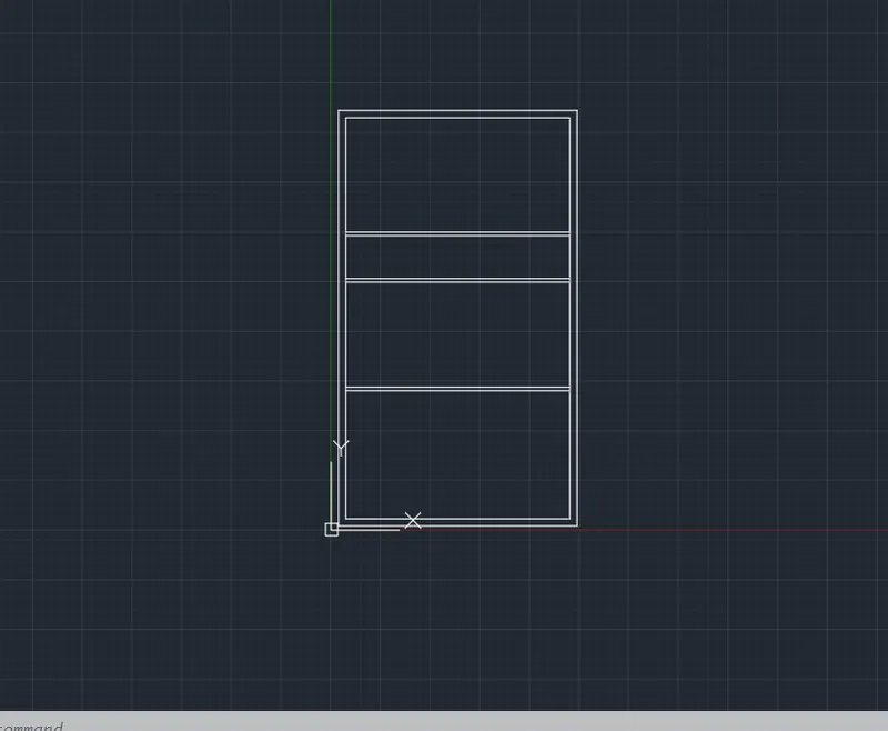
- Take offset 12'-0" from upper wall and wall offset take 4.5" fownward.
- Take again offset 4'-6" and wall offset 4.5" from last offset
- Again take offset 11'-0" internal wall 4.5" from last offset.
STEP-4
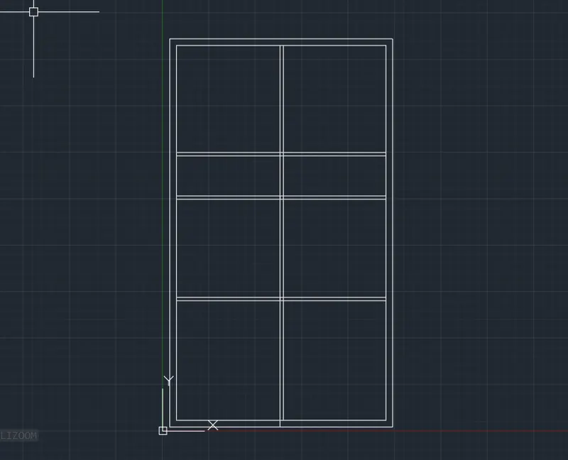
- Take vertical offset 11'-7.5" from vertical line , wall offset 4.5"
- Trim unwanted lines by using trim .
STEP -5
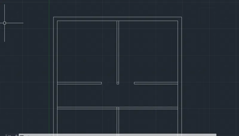
BED ROOM :
- Draw door D1 size of width 3' from upper first offset horizontal wall both side of center for bed room .
- draw toilet gate D2 size of width 2'-6" both of two toilet
(Gate drawing - for door designing take line of according to width and circle for arch and trim unwanted line.) - draw 1st toilet size of length 8'-3" width 4'-6" toilet and 2nd toilet lenght 8'-1.5" width 4'-6" width the help of extend and trim and line command,
STEP -4
DINING ROOM:
- The length of dining room 11'.-0" we alredy taken offset , than next take offset of 8'7.5" for width of room. and wall thickness 4.5" take.
LIVING ROOM:
- The length of dining room 11'.-0" we alredy taken offset , than next take offset of 14'-10.5" for width of room. and wall thickness 9" bottom side wall.
KITCHEN :
- Size of kitchen is length of 6'-8.0" take offset 6'-8.0" from dining room wall. dounward wall size 9" thickness.
- do kitchen openings assuning 5
STAIRS:
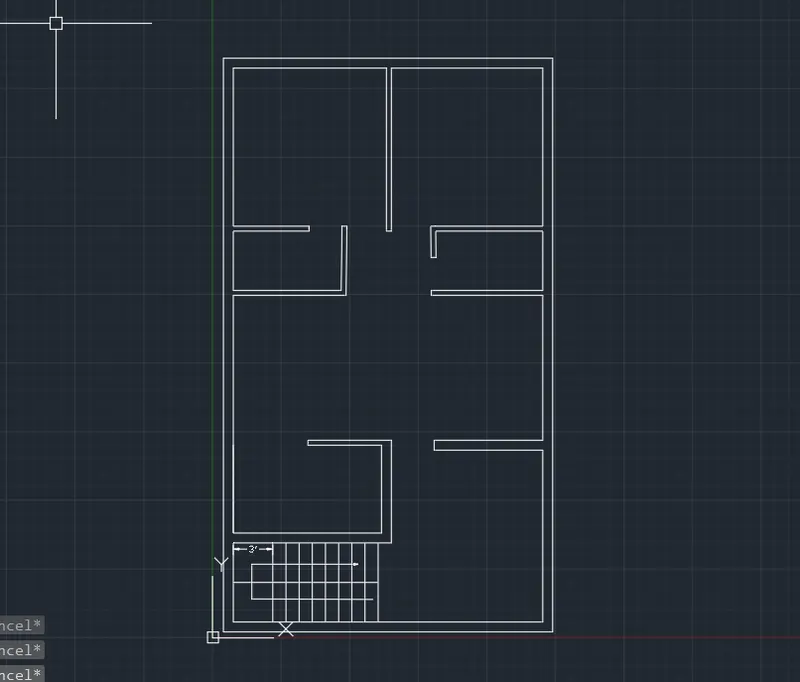
- For stair take offset 3' for the landing from verical corner part of the layout. and and for every riser give 1' or 10" riser 8 times from landing lin make staires.
- divide the stare 3' segment from center horizontal line.
- show line from entry to upward direction of stars with the help of line command.
PARKING AREA:
- Size of parking area Length 13'-9.5" width is 11'-9" including gate distance.
- this is alredy drawn because last part of the layout
- Make entry gate of layount , open the space 11'-9" for gate.
STEP-6
WINDOW AND DOOR :
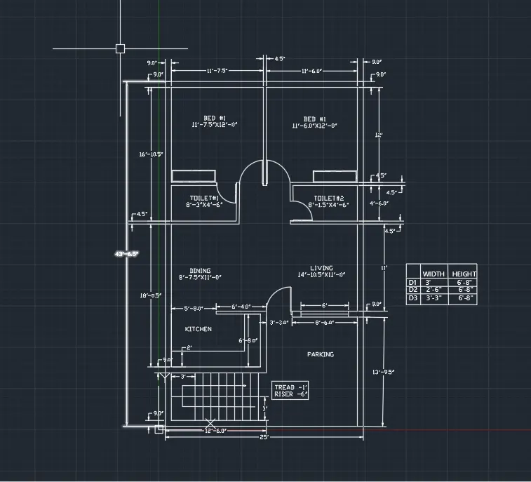
- with the help of line and circle commnand make door D1 = 3' of size from bedroom , D2 = 2'-6" toilet, D3 =3'-3" from after parking area entry main door.
- Put the window size of 6' width from side of D3 door of main door
- With the help of trim or erase command trim the all unwanted lines .
- With the Help of Dimention command show all the dimention for angular dimension use DIMD for Diameter and DIMRA for radius measurement
DRAWING NO. -2
FOR START ANY DRAWING FIRST OF ALL WE HAVE TO DO SOME SETTINGS ACCORDING THE DRAWING -
SETTINGS - OPEN AUTOCAD
- SET DEFAULT SETTINGS - METRIC (MM)
- SELECT A TEMPLATE - ACCORDING TO DRAWINGS
- SELECT A WIZAED - ADVANCED SETUP
- UNITS - DECIMAL , PRECISION -0
- ANGLE - DECIMAL DEGREES
- ANGLE MEASURE - ACCORDING TO PLAN
- ANGLE DIRECTION - COUNTER CLOCKWISE
- AREA - ACCORDING TO PLAN
After this enter "D" for dimention unit and set primary unit DECIMAL set precision 0.
MODES -
- GRID ON BY F7 'CONTROL+G'
- USE ORTHO MODE FOR STRAIGHT 90 DEGREE ACCRDING NEED(F8)
- ON POLAR TRACKING (F10) SET ANGLE (15,30,45)
- OBJET SNAP TRACKING (F11)
- OBJECT SNAP (F3)
- TRANPARANCY ON WHEN YOU NEED
TO DRAW THE UTILITY PLAN WE FOLLOW THE FOLLOWING STEPS : -
STEP-1
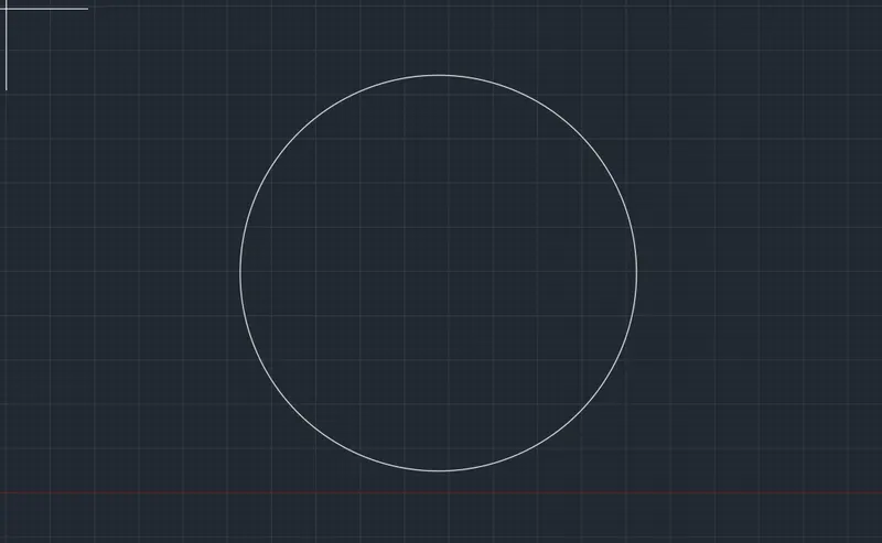
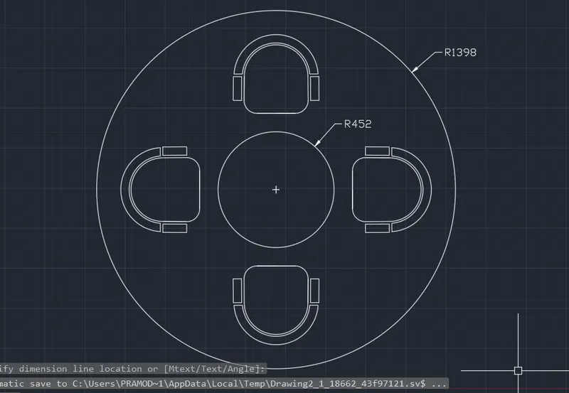
- Take circle command specify first point and draw circle with R1398 of radius.
STEP-2
- Again Take circle command to draw a circle of R452 radius with same center point.
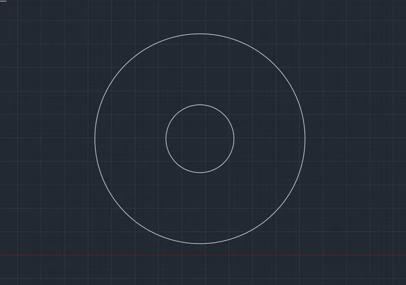
STEP-3
- take construction line and put it circle center point horizontally.
- and assume make 400 mm width of chair .and make rectangle of 400x 450 mm from this point
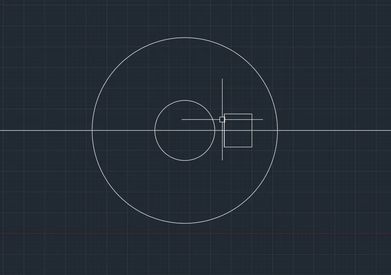
STEP-4
- draw the corner fillet by using fillet command of radius R50.
- make a circle of three point trim unwanted line bye using trim command .
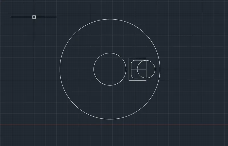
STEP-5
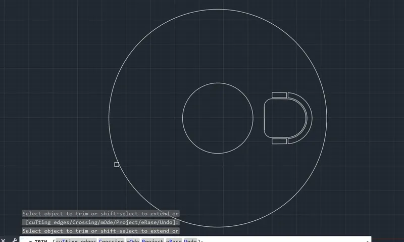
- take offset 15mm from outer side all outeer side of chair.
- take circular offsett 65mm of half circle.
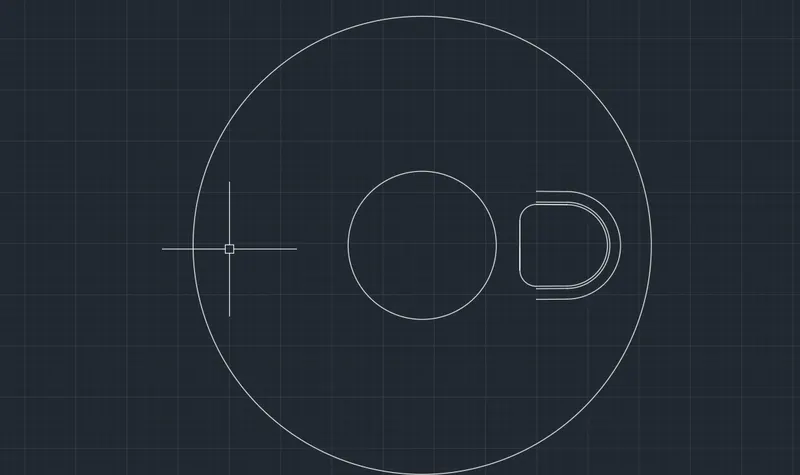
STEP-6
- by using trim commnd and line ccommand make the shape accurate given in the drawings.
STEP-7
- Take ARRAY command to make multiple object.
- First select the object type arraypolar in the command bar select arraypolar specify center point of circle
- than type no. of object 4.
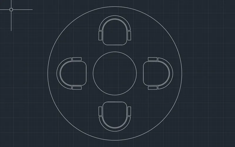
- With the help of trim or erase command trim the all unwanted lines .
- With the Help of Dimention command show all the dimention for angular dimension use DIMD for Diameter and DIMRA for radius measurement
DRAWING NO. -3
FOR START ANY DRAWING FIRST OF ALL WE HAVE TO DO SOME SETTINGS ACCORDING THE DRAWING -
SETTINGS - OPEN AUTOCAD
- SET DEFAULT SETTINGS - METRIC
- SELECT A TEMPLATE - ACCORDING TO DRAWINGS
- SELECT A WIZAED - ADVANCED SETUP
- UNITS - DECIMAL , PRECISION -0
- ANGLE - DECIMAL DEGREES
- ANGLE MEASURE - ACCORDING TO PLAN
- ANGLE DIRECTION - COUNTER CLOCKWISE
- AREA - ACCORDING TO PLAN
After this enter "D" for dimetion unit and set primary unit DECIMAL set precision 0.00
MODES -
- GRID ON BY F7 'CONTROL+G'
- USE ORTHO MODE FOR STRAIGHT 90 DEGREE ACCRDING NEED(F8)
- ON POLAR TRACKING (F10) SET ANGLE (15,30,45)
- OBJET SNAP TRACKING (F11)
- OBJECT SNAP (F3)
OTHER GIVEN DATA :
- OUTER WAL THICKNESS =300 MM
- INTERNAL WALL THICKNES = 150MM
TO DRAW THE UTILITY PLAN WE FOLLOW THE FOLLOWING STEPS : -
STEP -1
- Take onstruction line by enter command XL or from ribbon.
- Put it vertically and horizontally according to step one drawings.
STEP -2
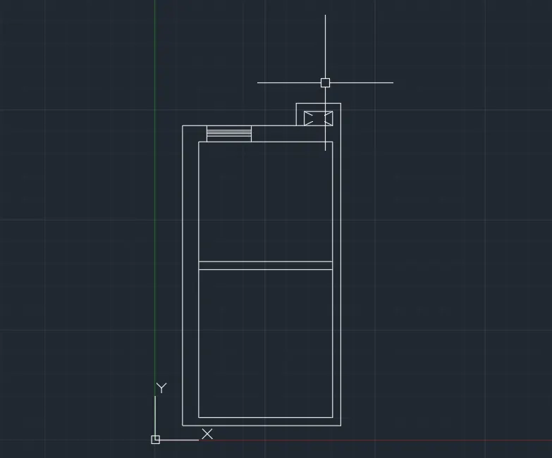
- Take offset 150 from horizontal line and 300 from vertical line for wall thickness.
- take offset of 1900 from vertical line to forward (x) direction and take 150 mm outer wall thickness
- Again take offset 2100 from down line to upward for utility room
- again take 150 mm wall offset. and take
- Take offset 1700 from vertical line uprward (y) Direction and take 300 for outer wall
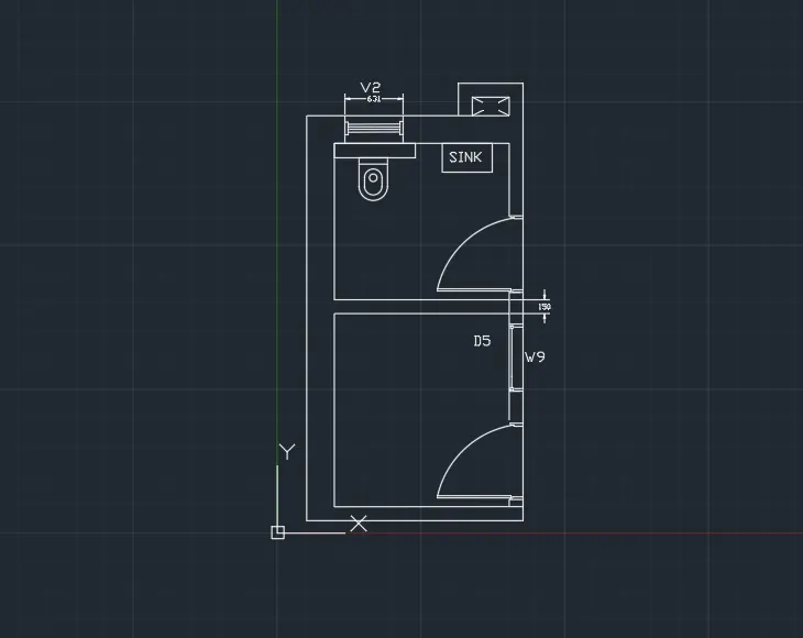
- make open outer part of the toilet size of 402x 201 than draw 150 mm wall outer side of the corner side.
- draw ventilation V2 in the D.H.TOILET distane of 150 mm outer wall.
- Trim unwanted line by using Trim command.
STEP -3
- with the help of line and circle commnand make DD.H. TOILET DOOR =832 MM of size UTILITY DOORD2 = 828
- Put the window size of W9 =728 width from side of D5 door of UTILTY ROOM
STEP -4
- With the help of trim or erase command trim the all unwanted lines .
- With the Help of Dimention command show all the dimention for angular dimension use DIMD for Diameter and DIMRA for radius measuremen
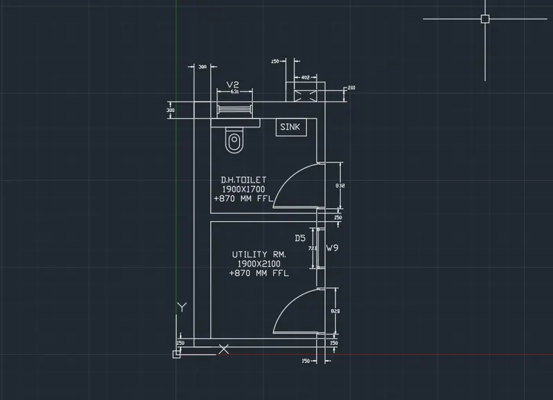
RESULT: COMPLETED THE ALL DRAWINGS WITH THE USING OF AUTOCAD SOFTWARE WITH GIVEN DIMENSION COMPLETED DRAWINGS ARE ATTACHED WITH THIS PROJECT BELOW RESULT.
RESULTANT DRAWINGS :
DRAWING NO. -1
DRAWING NO. -1
DRAWING NO. -1