Drafting of various geometries using Chamfer, Fillet tool in AutoCad
DRAFTING OF A VARIES GEOMETRIES DRAWINGS USING CHAMFER , FILLET AND OTHER TOOLS IN AUTOCAD .
SOFTWARE USED : AUTODESK AUTOCAD 2021
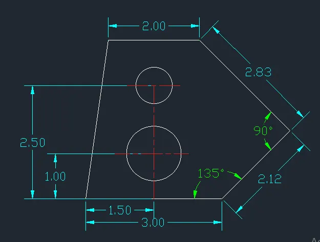
1) TO DRAW THE GIVEN DRAWING BY USING AUTOCAD SOFTWARE
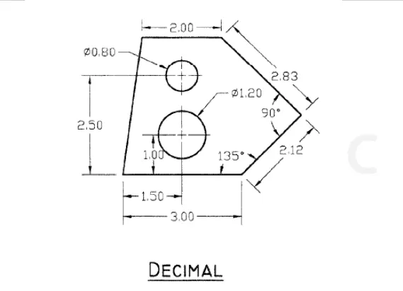
Aim: To create the above geometry
Procedure:
- First the open the software
- Give the command QNEW and press the ENTERE key
- Click on imperical templete
- Select ADVANCE SETUP
- Unit : decimal , precision :0.00
- Angle :decimal degree , precision :0.00
- Angle measure : East
- Angle direction : closkwise
- Area : 20*20
- And finished
- Lets start
Step:1
- create line by command "L" click on the first point( where we want to start) starting point :1,1 then give coordinate 3,0
- Then give the relative coordinate @2.12<45
- then specify next relative coordinate @2.83<135
- so the next coordinate will be @-2,2
- And the next coordinate is @-2,0
- Then click on "close"
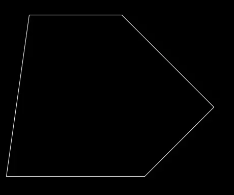
Step:2 : Creating circles
- Create an offset of 1 unit from the bottom line of 3 units ie, the centre of circle in y direction
- Enter the command "c" for circle by centre diameter method.
- With" OSNAP -midpoint on "move the mouse on the bottom line of 3 units,then the midpoint 1.5 unit will be snapped.
- Move the mouse vertically towards the above offseted line, so the centre of circle can be located (intersection of the tracked midpoint line and the offseted line)
- Click to specify the centre of circle and give the diameter as 1.2 units
- Similarly, give offset of 2.5 units from the bottom line of 3 units.
- Enter the command "c" for circle (centre- diameter method)
- Specify the centre by "OSNAP on" midpoint and move the mouse towards the line of 2.5 units
- Click on the centre and give diameter of 0.8 units
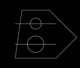
- Erase("e"-seelct the line) both the offsetted line
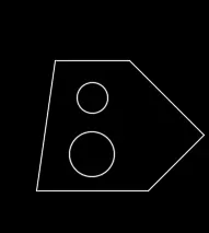
Result: The geometry is drawn
2) DRAW THE FOLLOWING FIG BY USING AUTOCAD SOFTWARE
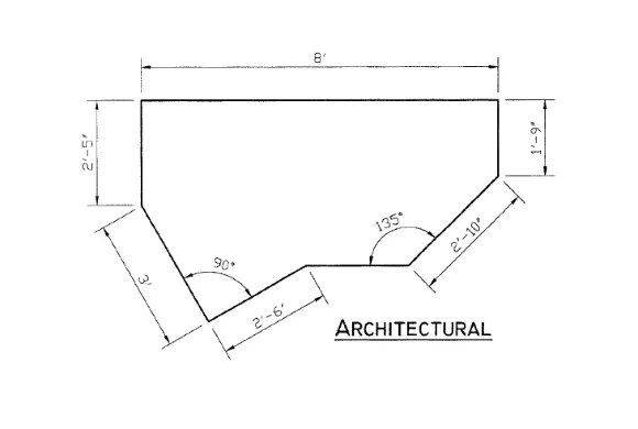
Aim: To crete the above geometry by Auto Cad tools
Procedure:
- First the open the software
- Give the command QNEW and press the ENTERE key
- Click on imperical templete
- Select ADVANCE SETUP
- Unit : Architecture , precision :0’-00”
- Angle :decimal degree , precision :0.00
- Angle measure : East
- Angle direction : closkwise
- Area : 20*20
- And finished
- Let’s start
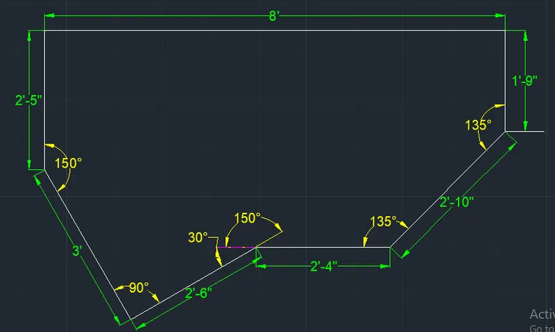
- Draw line of length 2'6' with angle 210 degree by using line command
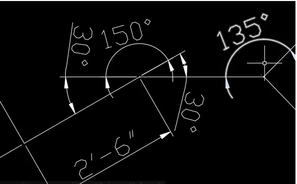
- With angle as 90 degree draw another line of length 3'.
- With ortho ondraw a line of length 2'5" vertically
- Draw another line of 8" vertically.
- Draw another line of 1'9" vertically downwards.
- With line command extend the horizontal with by the first pointThen use line command and draw line of 2'10' from the last point of 1'9" length meeting the horizontal such that the included angle is 135 degree.
Result: The geometry is drawn:
3) DRAW THE FOLLOWING DIAGRAM BY USING VARIOUS COMMAND AND TOOLS IN AUTOCAD
Aim: To create the geometry
Procedure:
- First the open the software
- Give the command QNEW and press the ENTERE key
- Click on imperical templete
- Select ADVANCE SETUP
- Unit : Engineering , precision :0’-00”
- Angle :decimal degree , precision :0.00
- Angle measure : East
- Angle direction : closkwise
- Area : 20*20
- And finished
- Let’s start
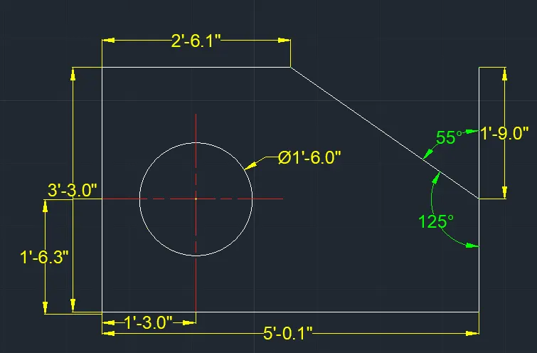
Step:1 Create a rectangle
- Command "REC" - click on a point where we nedd to place rectangle
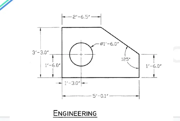
- Click on "dimension" give the length as 5'0.1" and width as 3'3". and create rectangle
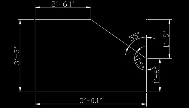
- Use command "CHA" for chamfer
- Click on "ANGLE",
- Then specify the distance of first line to be chamfered- give it as 1'9" ([3'-3"] - [1'-6"] = 1'-9")
- Then specify the chamfer angle from the first line as 55 degree ie, (180-125 = 550)
Step:2 Create Circle
- Comment "EXPLODE" and click the rectangle,so that each line can be selected seperately.
- Drawn an offset of 1'6" vetically and 1'3" horizontally from the side of rectangle
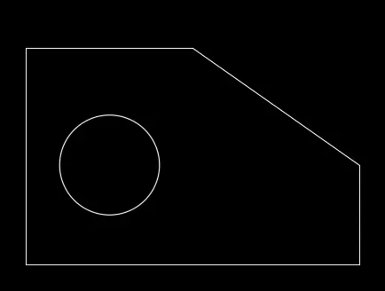
- Create circle with centre-diametr method, the intersecting of two offseted line will be the centre
- Command "C" - specify centre- click on intersecting lines
- Click on "dimaeter" and give the value as 1'6"
- Erase both the offsetted lines by command "E" select the objects and press enter.
Result: The geomerty is drawn.
4) CREATE THE FOLLOWING GEOMATRIC FIG BY USING AUTOAD SOFTWARE
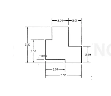
Aim: To create the geometry
Procedure:
- First the open the software
- Give the command QNEW and press the ENTERE key
- Click on imperical templete
- Select ADVANCE SETUP
- Unit : decimal , precision :0.00
- Angle :decimal degree , precision :0.00
- Angle measure : East
- Angle direction : closkwise
- Area : 20*20
- And finished , lets start
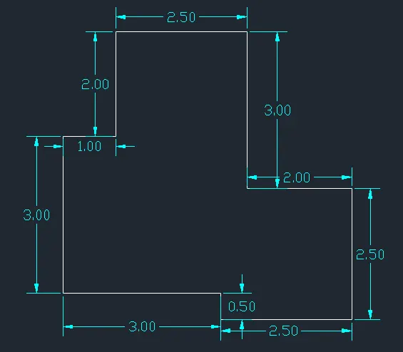
-Here we are drawing by using polyline.
Step:
- Use command "PL" for polyline and give the direction by moving the cursor to the desired position.
- To draw ab move the cursor to - x direction and give 3 units.
- To draw bc move cursor to + y direction and give 3 units
- To draw cd,point cursor to + x direction and give 1 unit
- To draw de,point cursor to + y direction and give 2 unit
- To draw ef point the cursor to + x direction and give 2.5 units
-To draw fg point the cursor to - y direction and give 3 units.
- To draw gh point the cursor to+ x direction and give 2.5 units
- To draw hi, point the cursor toward-y direction and give 2.5 units.
- To draw ij ,point the cursor towards - x direction and give 2.5 units
- To draw ja point the cursor to + y direction and give 0.5 units.
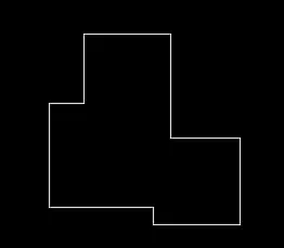
Result: The geometry is drawn
5) DRAW THE GIVEN FIG IN AUTOCAD SOFTWARE BY USING TOOLS IN AUTOCAD
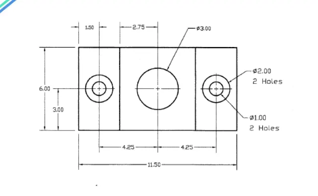
Aim: To create the geometry.
Procedure:
- First the open the software
- Give the command QNEW and press the ENTERE key
- Click on imperical templete
- Select ADVANCE SETUP
- Unit : decimal , precision :0.00
- Angle :decimal degree , precision :0.00
- Angle measure : East
- Angle direction : closkwise
- Area : 20*20
- And finished , lets start
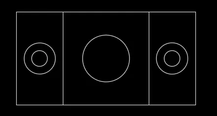
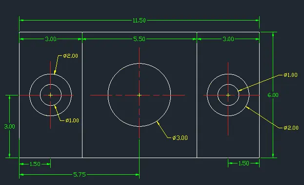
Step:1 Draw a rectangle
- Command "REC" click on the point where we want to create rectangle
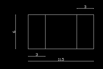
- Give length as 11.5 units and width as 6 units
- Use command "EXPLODE" to make the rectangle into different line segments. Offset both vertical side of rectangle to a distance of 3 units command "o" - give ofset distance as 3 units
Click inside the rectangle as the offseted line will be formed.
Step:2 Creating the circles - centre circle
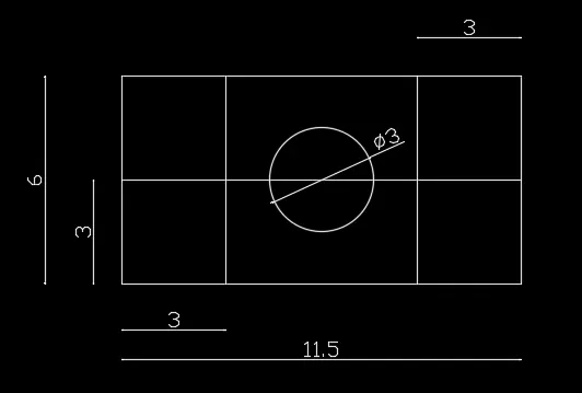
- Make an offset 3 units from the bottom line of rectangle command "O" -distance = 3 units.
- Command "c" -specify the centre of the circle by "OSNAP ON" and by dragging the cursor along the top line of rectangle
- As the snap is on the midpoint of the line is snapped
- Then move the cursor downwards towars the offseted line,then click on the line and specify the centre of circle
- Clickon "dimaeter" and give 3 units.
Step :3 Creating other two circles
- Give offset 1.5 units on both vertical sides -"0" - offset distance =1.5 units
- The intersecting line of both the horizontal offseted line(3units) and the vertical offseted line(1.5 units) will be the centre of circle
- With centre and diameter method, circle is drawn
- Command "C" - specify the centre and give the diameter as 2 units
- The inside circle is drawn with same centre and diameter as 1 unit.
- Copy the 2 circles "CO"- specify base point- centre of circle is picked and placed in the intersection if the offseted line.
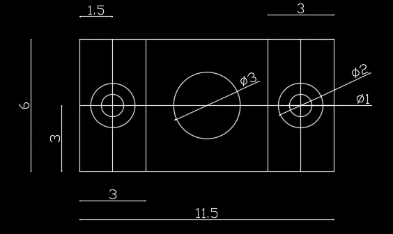
- Erase the offseted lines -"E" - select the objects and press enter
Result: The geomerty is drawn:
6) CREATE THE FOLLOWING GEOMETRICS BY USING AUTOCAD SOFTWARE
Aim: To create the geometry.
Procedure:
- First the open the software
- Give the command QNEW and press the ENTERE key
- Click on imperical templete
- Select ADVANCE SETUP
- Unit : decimal , precision :0.00
- Angle :decimal degree , precision :0.00
- Angle measure : East
- Angle direction : closkwise
- Area : 20*20
- And finished , lets start
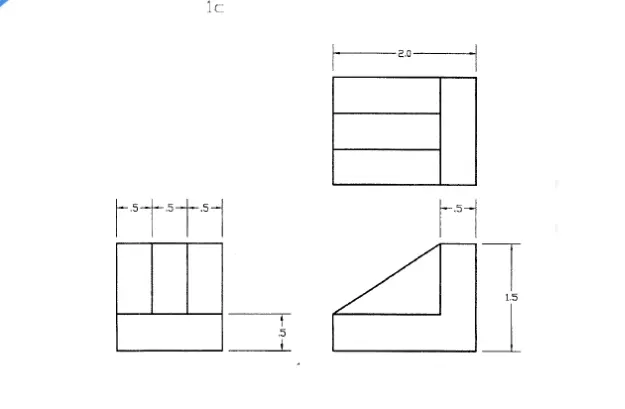
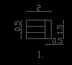
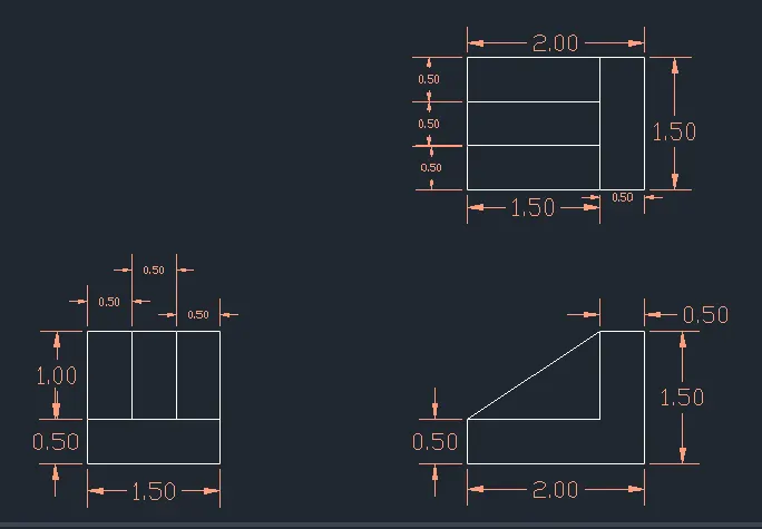
Step: 1 To draw 1.
- Line command "L" pick a point, give 2 units to + x direction and 1.5 units -y direction,2 units to -x direction and "CLOSE"
- Make offset "O" -offset distance =0.5 units and give 2 lines as offset in y direction.
- Make offset from the right side line of unit 0.5 by command "O" and specifying the distance
- Trim the excess lines by command "TR" - select the bese point ( till where we want to trim) and seelcting the line we need to trim.
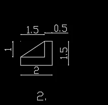
Step:2 To draw 2.
- Command "L" specify the first point as a projection of 1st figure by using object snap
- Give the distance as 1.5 units in - y direction and 2 units in - x direction
- Dive 1.5 units in + y direction and 2 unit in + x direction , thus forming a rectangle
- Use commans "CHA" to chamfer,give the 1st distance as 1 units and 2nd distance as 1.5 units.
- Use command "L" and join the end point of the chamfered line,thus forming a traingle at the top.
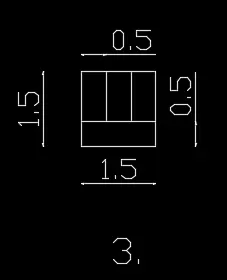
Step:3 To draw 3
- Draw line "L" and specify the first point by projecting the line of 2nd figure by using "OSNAP"on.
- With using line command draw a rectangle of side 1.5 units (1.5 unit in -x direction,-y direction,+x direction and + y direction)
- With the command offset "O" from the bottom line give an offset distance of 0.5 unit.
- Also give offset distance 0.5 unit from the left side ofthe rectangle
- Trim the unwanted lines by using command "TRIM" select the base line enter and select the unwanted lines and give enter.
Result: The geometry is drawn:
7) DRAW THE FOLLOWING GEOMATRIC FIG USING AYTOCAD SOFTWARE
Aim: To create the geometry.
Procedure:
- First the open the software
- Give the command QNEW and press the ENTERE key
- Click on imperical templete
- Select ADVANCE SETUP
- Unit : decimal , precision :0.00
- Angle :decimal degree , precision :0.00
- Angle measure : East
- Angle direction : closkwise
- Area : 20*20
- And finished , lets start
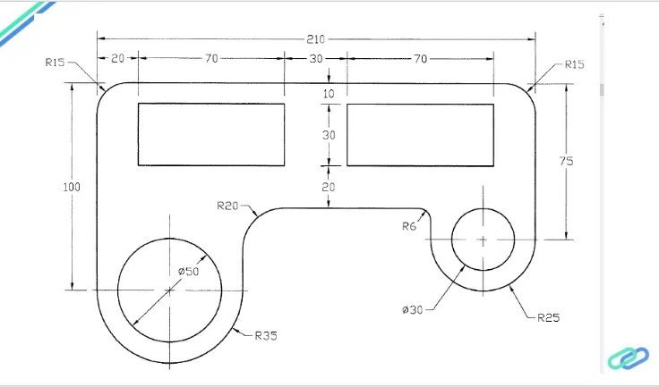
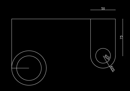
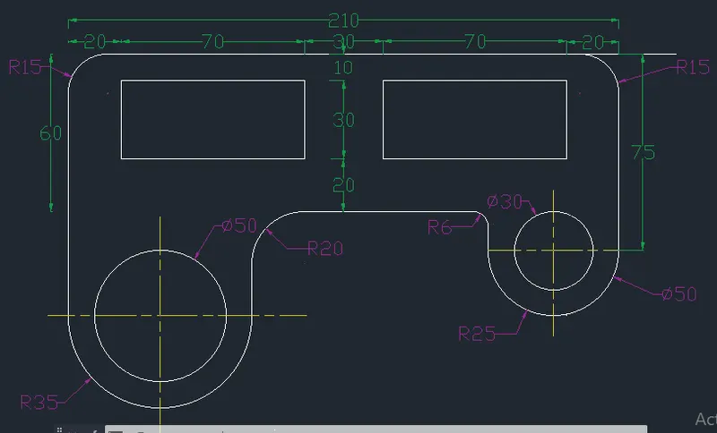
- Draw circle of radius 35 and another circle with same centre with dimaeter 50. Command "c" specify centre and give radius.
- Draw line with command "L" along the diammeter of the circle and then vertically upwards give distance as 100 nits,then + x axis a distance of 210 units and 75 units in - y direction.

- Draw offset 50 units (25+25=50, radius of arc) from the 75 unit line
- By arc strat,end radius, draw an arc with the start point as the endpoint of 50 unit offseted line and the endpoint of 75 units.
- By the same centre, draw a circle of dimatere 30 units.
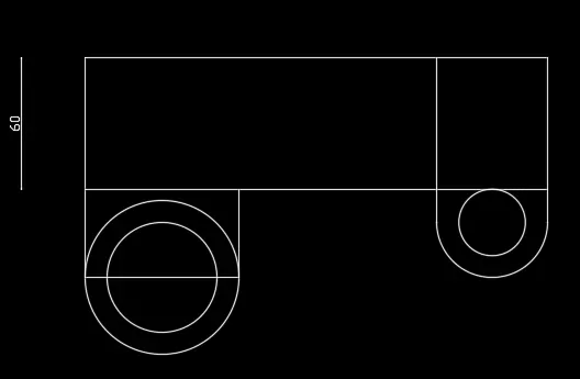
- Draw offset 60 units from the top.
- From the extended line from the 50 diameter circle draw line meeting the offseted line of 60 units.
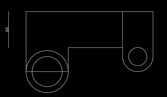
- Delete the offseted line and continue the line horixontally until it meets the end of the arc created of radius 25.
Drawing rectangle:
- Give offset of 20 units from the left side of the figureand 10 units from the top.
- Then draw rectangle with command "REC" specify the corner point as intersection of offseted lines.
- select "Dimension" and give the dimesion as 70 unit and 30 units.
- Similarly on the other side right create an offset of 20 units and copy the rectangle created earlier.
- Delete the offseted and unwanted lines.
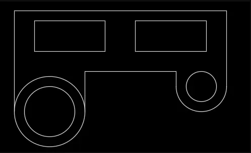
- Trim the part of circle of radius 35 units so that it froms an arc.
- Then fillet the corners : Command "FILLET" click on radius and give the radius ,then select the two lines of which the corners are to be filleted.
-For the left and right side of the figure give 15 units as fillet radius
-Give fillet radius as 20 units and 6 units in the bottom side.

Result: The geometry is drawn
8) DRAW THE GEOMETRIC FIG BY USING THE AUTOCAD SOFTWARE
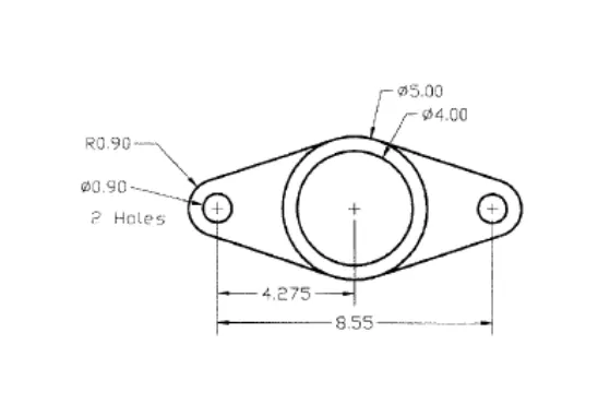
Aim: To create the above geometry.
Procedure:
- First the open the software
- Give the command QNEW and press the ENTERE key
- Click on imperical templete
- Select ADVANCE SETUP
- Unit : decimal , precision :0.00
- Angle :decimal degree , precision :0.00
- Angle measure : East
- Angle direction : closkwise
- Area : 20*20
- And finished , lets start
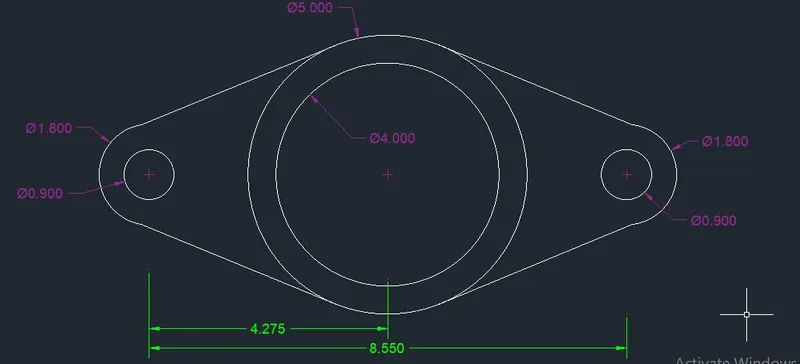
Step:1
-Draw circle of dimater 4 units "c"- specify centre-click on "diameter" -give 4 units.
- Draw another circle of diameter 5 units with same centre - command "C" with osnap centre on - specify the centre- click on diameter give 5 units
- Draw a line of 4.275 units from the centre of circle- "L" - cursor is pointed to direction and give 4.275 units.
- Consider this as the centre of third circle with command "C" - specify the centre end of line and click on diameter and give 0.9units
- With same centre of circle four,drawn another circle with radius =0.9 units,Command-"C" -specify centre and give the radius as 0.9.
- Mirror the two circles drawn on the other side -"MI"- select both the object-enter - specify the point of mirror line -mirror line is drawn vertically from centre of 5 unit circle and give erase the source object as no.
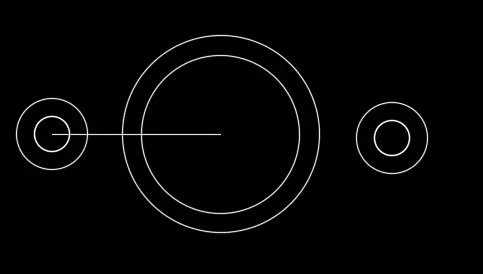
- With polyline draw tangent to the fourth circle of radius 0.9 and the first circle of diameter 5 units in top and bottom on both sides. with "OSNAP" tangent -on
- Delete the line drawn for refernce and trim the unwanted part of circle by command "TR"- specify the base object ‚seelct the tangent line -seelct the object to be trimmed- select the circle and enter.
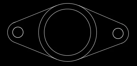
Result: The geometry is drawn:
9) CREATE THE FOLLOWING FIG BY USING VARIOUS TOOLS IN AUTOCAD SOFTWARE
Aim: To create the geometry.
Procedure:
- First the open the software
- Give the command QNEW and press the ENTERE key
- Click on imperical templete
- Select ADVANCE SETUP
- Unit : Architecture , precision :0’-00”
- Angle :decimal degree , precision :0.00
- Angle measure : East
- Angle direction : closkwise
- Area : 20*20
- And finished
- Let’s start
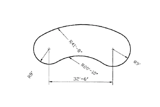
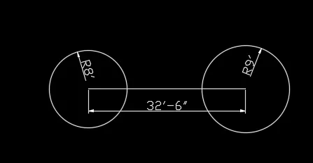
- Draw a line 32'6" ,then draw two circles of radius 8' and 9' with centre as
- To draw the bottom arc, draw offset to both the circles with offset distance as radius of the bottom arc.
- Command "o"- select the circle -give offset distance as 20'10".
- We will get an intersection of the two circles, from the intersecting point draw a line to the centre of the circle of radius 8' and 9'.
- The line meeting the circles will act as the tangent of the circle and its distance will be 20"10' same as the radius of arc. By using tan tan radius option for draw circle
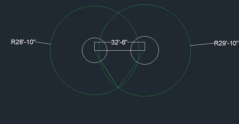
- Draw a circle with centre as intersection point of the offseted circle and radius of 20'10".
- It will pass through the tanget points
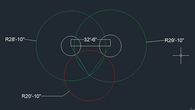
- Trim the rest of the figure to get an arc and thus an arc of 20'10' will be formed.
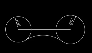
- To draw the upper curve,
- Draw a circle with radius 32'8" (41'8'-9'=32'8") with centre same as that of radius 9' circle.
- Draw another circle with radius 33'8" (41'8'-8'=33'8") with centre same as that of radius 8' circle. (so that the distance from the newly drawn crcle to the upper side of radisu 9' and 8' circle will be 41'8".)
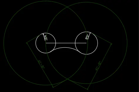
- Draw perpendicular lines from the bottom intersection of both circles andthrough the centre to top of the circle of radius 8' and 9', which indicates the tangent points.
- Draw another circle, with centre as the intersecting point of the bottom circles and with radius 41'8".
- It passes through the tagent lines drawn earlier.
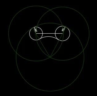
- Trim off the rest, so that an arc of radius 41'8" is fromed between the tangents.
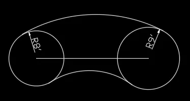
- Trim the part of the circle and the line connecting the centre of circles.
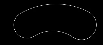
RESULT: The geometry is drawn.
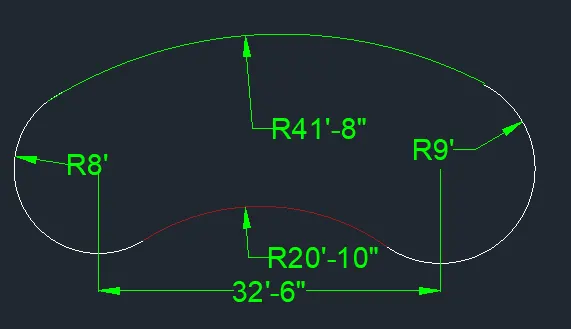
10) CREATE THE FOLLOWING FIG BY USING VARIOUS TOOLS IN AUTOCAD SOFTWARE
Aim: To create the geometry.
Procedure:
- First the open the software
- Give the command QNEW and press the ENTERE key
- Click on imperical templete
- Select ADVANCE SETUP
- Unit : decimal , precision :0.00
- Angle :decimal degree , precision :0.00
- Angle measure : East
- Angle direction : closkwise
- Area : 20*20
- And finished , lets start
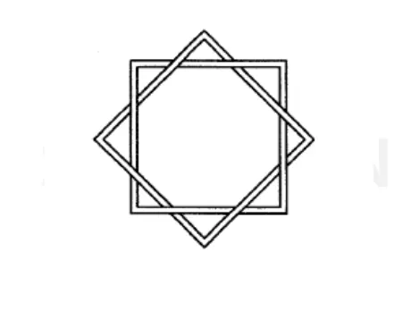
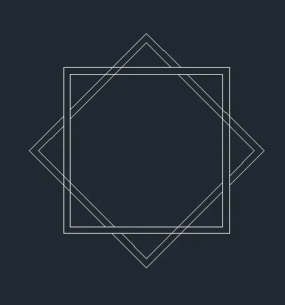
By rectangle tool draw square
- Command "REC" - specify the point where we need to draw -click on "dimension" - here I have taken as length=5 units and breadth=5units.
- Take offset of 0.2 units outside the rectangle ,Command "O" - specify the distance =0.2 units.
- Create another rectangle os same size as in first step

- copy this sqaure,so that two squares are created.
- Rotate the second square by command "RO"- select the object-specify the base point -bottom point(The point by which we need to rotate) and rotate it by angle 45 degree
- With OSNAP on move the rectangle by command "M"- select object- specify base point (here base point is selected as centre of square) and is moved and placed onbcentre of the first square by using osnap centre on
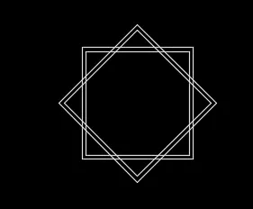
- Trim off the overlapping lines alternatively by comand "TR"- double enter
Result: The geometry is drawn
11) CREATE THE FOLLOWING FIG BY USING VARIOUS TOOLS IN AUTOCAD SOFTWARE
Aim: To create the geometry.
Procedure:
- First the open the software
- Give the command QNEW and press the ENTERE key
- Click on imperical templete
- Select ADVANCE SETUP
- Unit : Architecture , precision :0’-00”
- Angle :decimal degree , precision :0.00
- Angle measure : East
- Angle direction : closkwise
- Area : 20*20
- And finished
- Let’s start
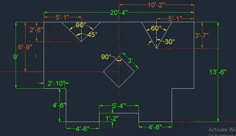
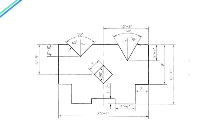
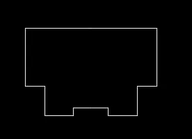
By using line command,draw the outline
- Command "L" - give the distance of 2'8"(10'2"- 【4'6"+3')) to + x direction
- With cursor pointing to - y direction give a distance of 1'2"
- With cursor pointing to + x direction draw a line of 4'6"
-With the cursor pointing to + y directio draw a line of 4'6" (13'6"-9")
- draw 3' in + x direction
- Draw 9' in + y direction.
- Draw 10'2" in - x direction
- With command "M" mirror the image, Command "M" - select the object- select the base point and give the mirror line -and click no so that the orginal object won't get erased.
- Give offset line of distance 3'7" horizontaly by offset command "0"
- With midpoint of 10'2' draw a verical line of length 3'7"
- Draw lines on both sides such that the includedangle is 60 degree 30 degree on both side of the vertical line.
- Similarly on the other side,locate the midpoint,draw a vertical line of 2'8"and draw the inclined lines such that the included angle is 90degree
- Draw a line vertically downwards from the midpoint of the object (10'2") and offset the top line at a distance of
- Draw a line vertically downwards from the midpoint of the object (10'2") and offset the top line at a distance of 6'9" so that the centre point of the square is located.
- With command "polygon" draw a polygon of 4 sides,specify centre and give radius as 1.5' circumscribed inside a circle.
- Rotate the polygon to 45 degree with base point as\ centre
- Erase all the lines used for reference.
Result: The geometry is drawn