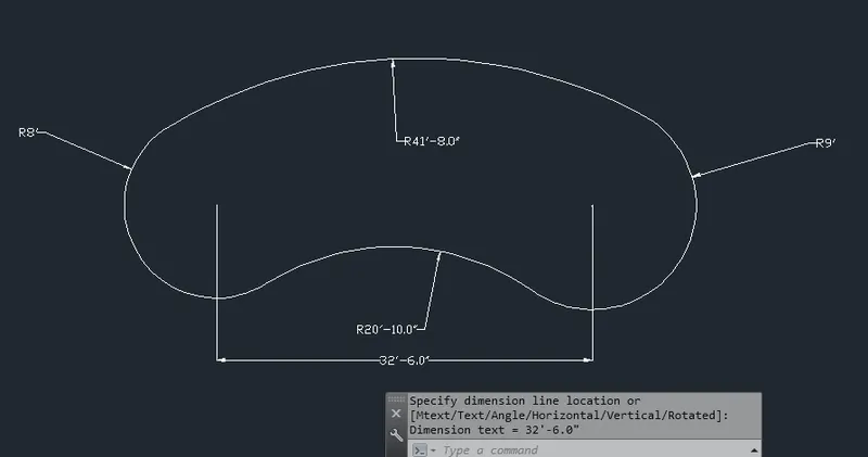
Drafting of various geometries using Chamfer, Fillet tool in AutoCad
Drafting of various geometries using chamfer, fillet tool in autocad
Aim: To draw given geometry by using chamfer and fillet tool in autocad
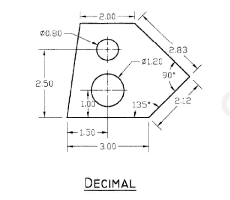
Step1
- Go to start menu, select autocad 2014
- In the command line type Startup
- Enter new value of startup 1
- Go to application menu and select new
- In the create new drawing dialogue box, we do the advance setup and select the decimal unit of measurement
- Set the limits by entering limit in the command line lower left corner spaced is 100 and upper left corner space is 100
- Enter unit command in command tab
- In the drawing units dialogue box, select decimal type, 0.00 in precsion, and meters in insertion scale
Step2
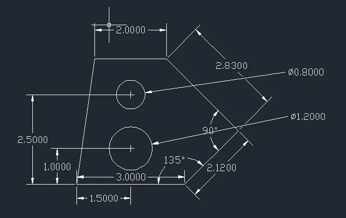
- Draw a line by using line command of length 3units
- Select chamfer angle command and give length of the chamfer is 1 and angle 45 degrees
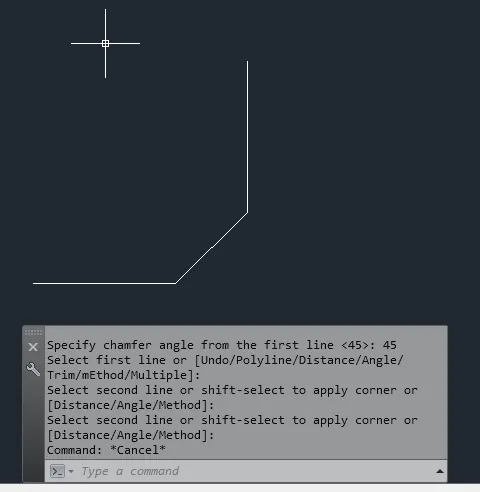
- Extend the chamfered line to 2.12units and trim out the remaining lines
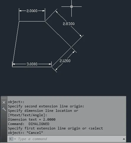
- Measure the distance by using dimaligned tool
Step3
- Draw a perpendicular line to the chamfered line of 90Degrees
- And continue to draw a line of given line lengths
- finally join close the line to the end point
- Measure the geometry using dimension command
Step4
- Draw a circle of diameter 0.8mm on the midpoint of 2.5mm line inside the geometry
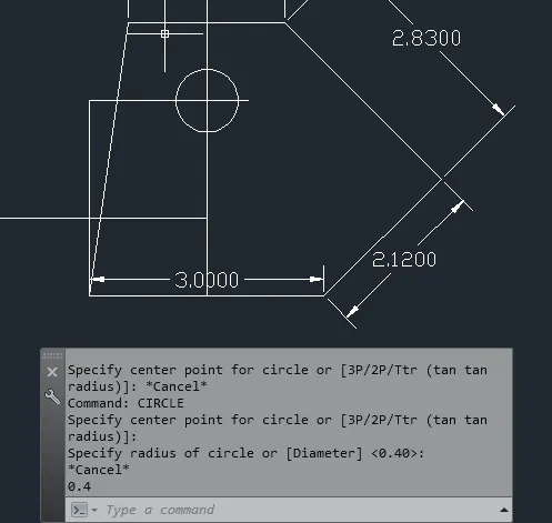
- Measure the diameter of circle by using diameter dimension
- Again draw a circle of diameter 1.2mm inside a gemetry on the midpoint of 1mm line
- Measure the diameter of a circle by using diameter dimension tool
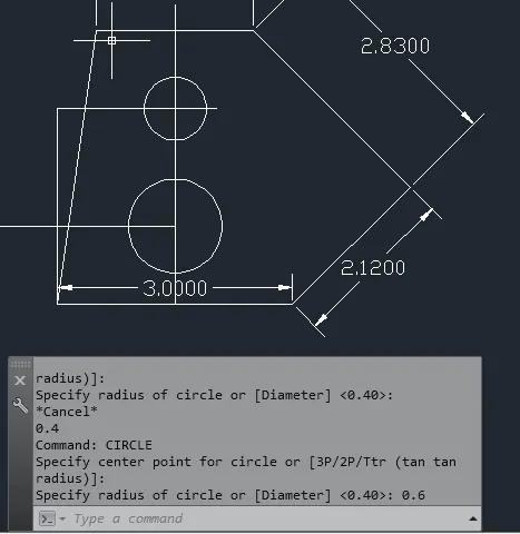
- And also measure angle between the chamfered line and perpendicular line that is perpendicular to chamfered line
Result:
Step1
- Take a new drawing by taking startup command, give startup value 1
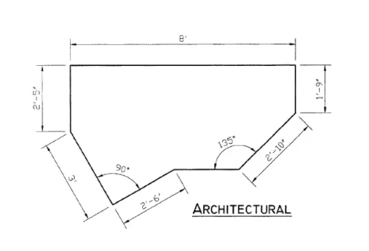
- Set the units to architectural unit system and precision to 0'0"
- Set the limits, give upper right corner 100', give lower left corner 100'
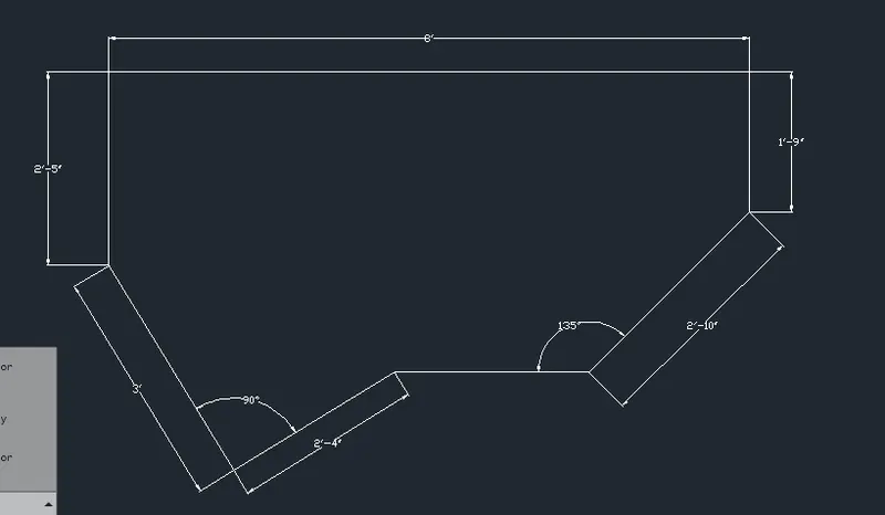
- Take line command and draw a line using relative coordinate system of length 2'10" @ an angle of 45degrees
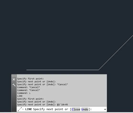
- Again take a line command and draw a line of length 1'9" in positive vertical axis
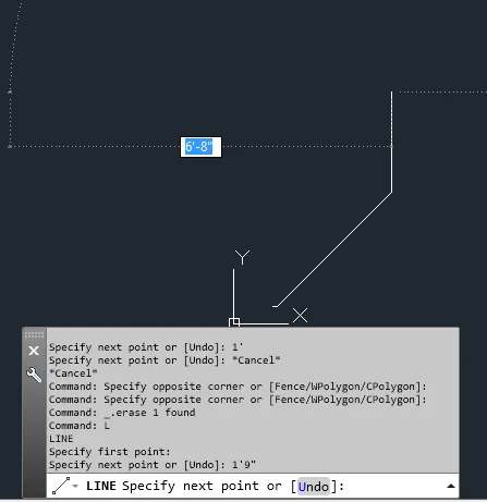
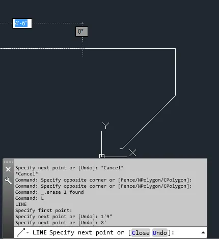
- Again take a line and draw a line of length 8' in negative x axis
- Again take a line command and draw a line of length 2'5" in negative vertical axis
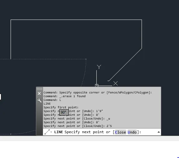
- Take a line command and draw a line of length 3' and again draw a line of length 2'6" and finally join the end point
- Take a dimaligned command and measure the distance between the lines and dimension them
- To measure angle take a dimangular command and measure the angle between two lines
Result
3)
Step1
- Go to application menu and take a new drawing and create new drawing dialogue box will open and set a unit to engineering units and precision to 0.00
- Set a limits by giving lower left corner to 100' and upper right corner to 100'
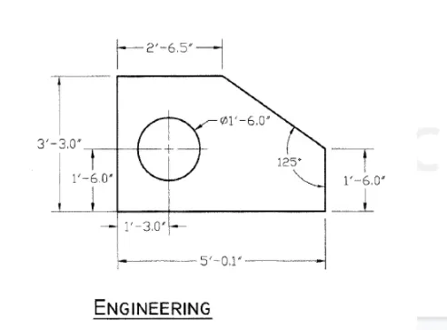
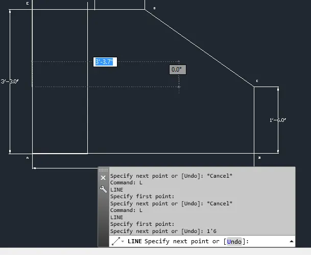
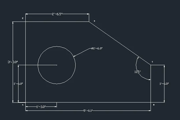
- Take a line of length 5'0.1" by using line command in positive X axis
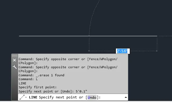
- Take a line command a draw a line of length 1'6" in the positive Y axis
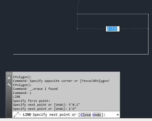
- Take a line of length 3'3" in the positive Y axis and draw a line
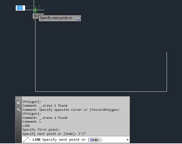
- Take a line of length 2'6.5" and draw a line in positive x axis
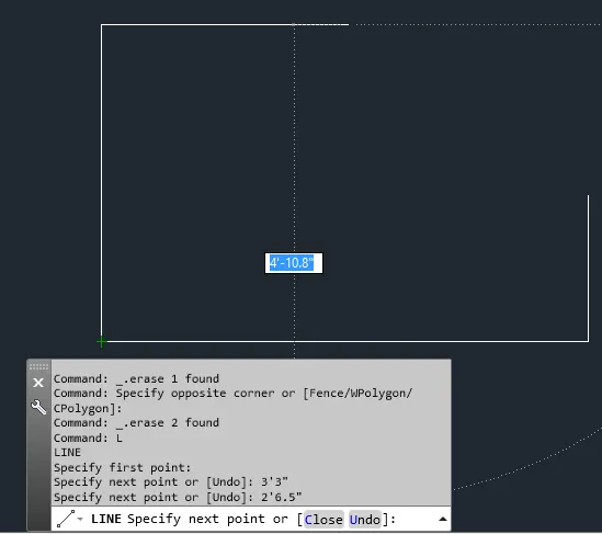
- Finally close the line to the start point
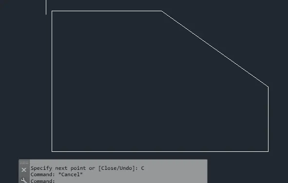
- Finally measure the dimensions by taking dimension command and measure the distance
- And name the corners as A,B,C,D and E
Step2
- Draw a line of length 1'3" from the A point to draw a circle inside the object
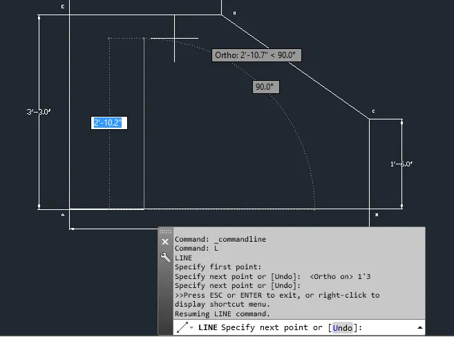
- Again draw a line from the A point in positive Y axis to draw a circle inside the object
Step3
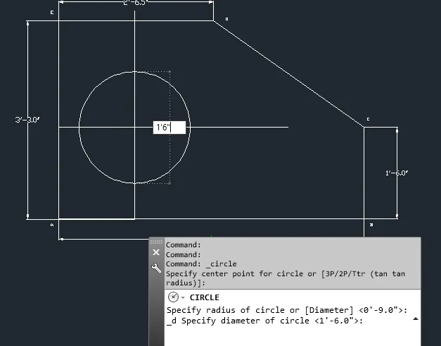
- Draw a circle of diameter 1'6" from the midpoint of the line that we drawn from the point A
Result
4)
Step1
- Go to application menu and take a new drawing
- Create new drawing dialogue box will open and set the units to decimal and precision is 0.0
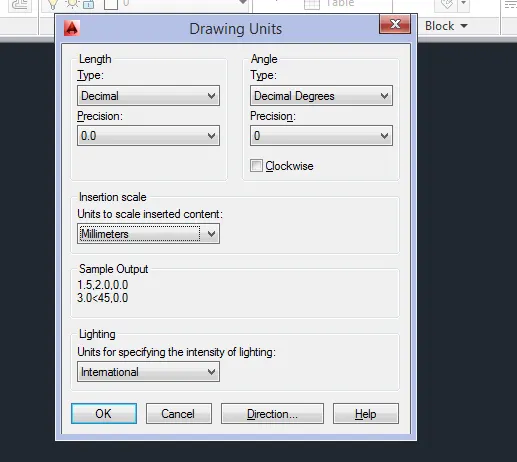
- Set the units by unit command for decimal and precision 0.0 and insertion unit as millimeter
- Set the limits to 100' and 100'
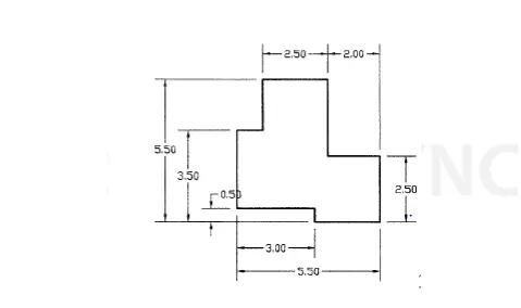
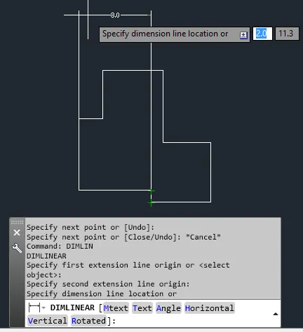
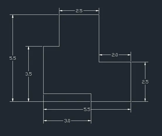
- Take a line command and draw a line of length 5.50mm in positive x axis
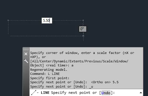
- Take a line of length 2.50mm in positive Y axis
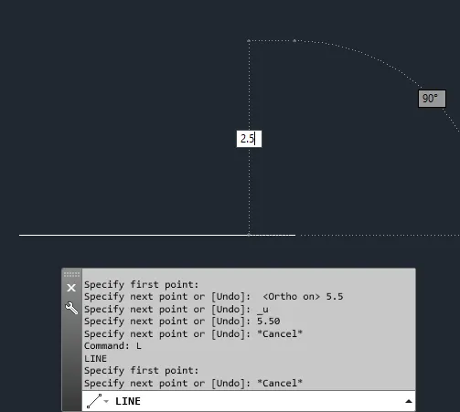
- Take a line command and draw a line of length 2.00mm in negative x axis
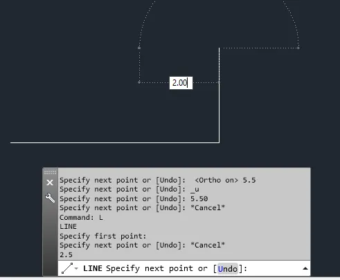
- Take a line command and draw a line of length 3mm in positive x axis
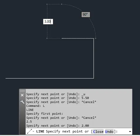
- Continue the line command draw a line of length 2.5mm in negative x axis
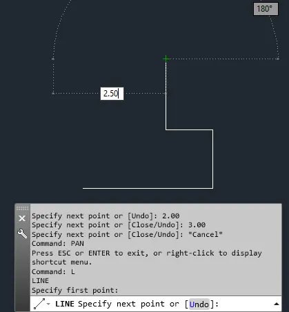
- Mark the length of 3mm by using line command from the start point to take a length of 0.5mm from end point
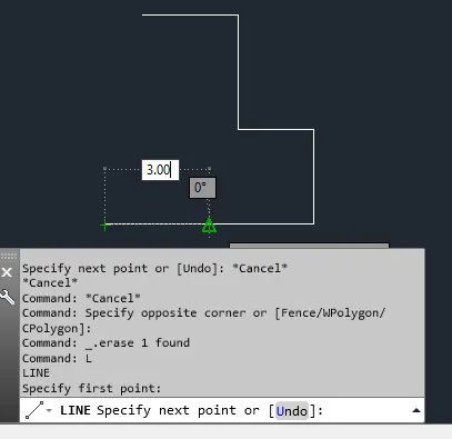
- Take a line of length 0.5mm from the 3mm line that was drawn earlier
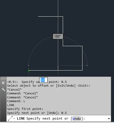
- Draw a line of length 3mm from the 0.5mm line
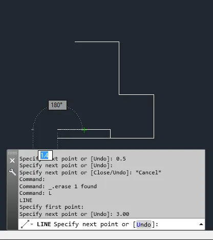
- Trim the below line by using trim command
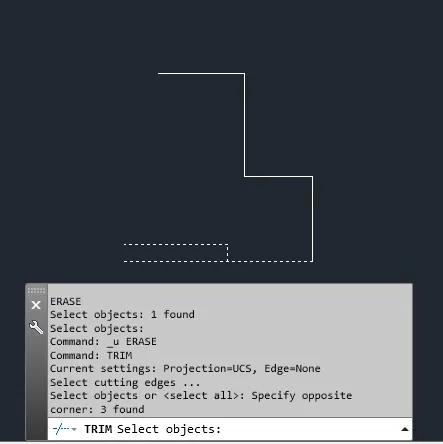
- Draw a line vertically upwards of length 3.00mm
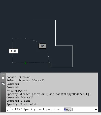
- Draw a line vertically downwards of length 2mm
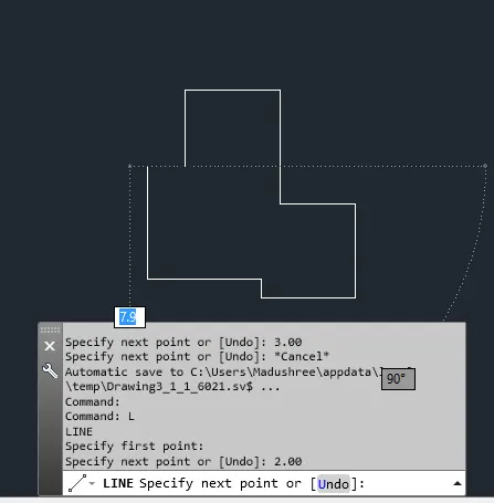
- Finally close the line of the object
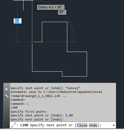
- And dimension the lines by using dimension command
Result
5)

Step1
- Continue with the decimal units precision to 0.0 and insertion scale as millimeters
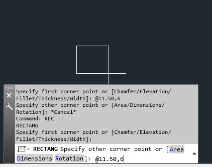
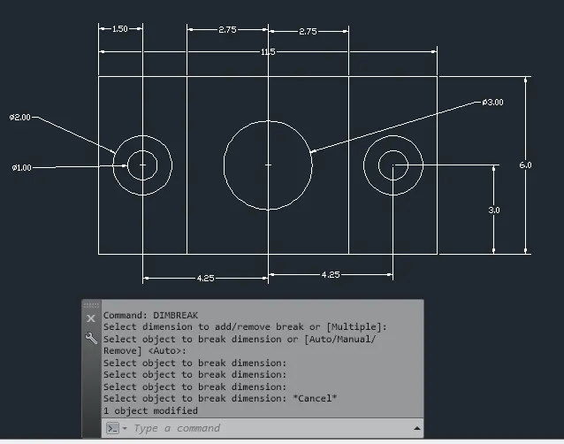
- Draw a rectangle by using rectangle tool of length 11.50mm and width as 6mm
- Mark a line in the midpoint of the rectangle
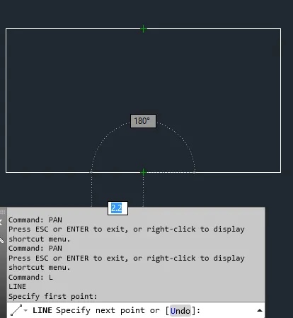
- Draw a line of length 2.75mm from the centre of the rectangle both the sides
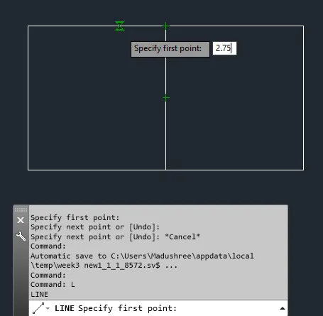
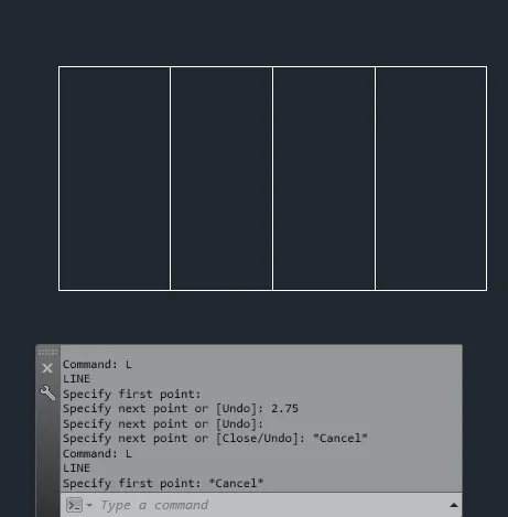
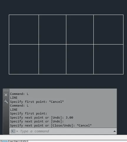
- Draw a line of length 3mm from midpoint of the rectangle in width side
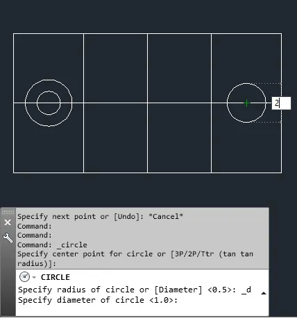
- Draw a circle of diameter 2mm to the midpoint of line and 1mm inside of 2mm circle both the sides
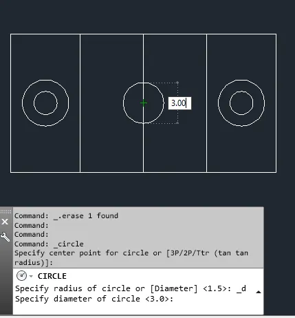
- Draw a circle of diameter 3mm by taking circle tool in the midpoint of line
- Finally give the dimensions to all the objects using various dimension tool such as diameter to measure the dia of a circle and dimlinear to measure the distance between the lines
Result
6)
Step1
- Continue with the same drawing sheet because the given drawing is in decimals as same as the previous drawing
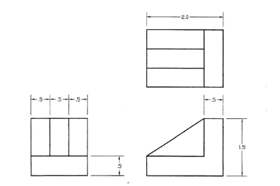
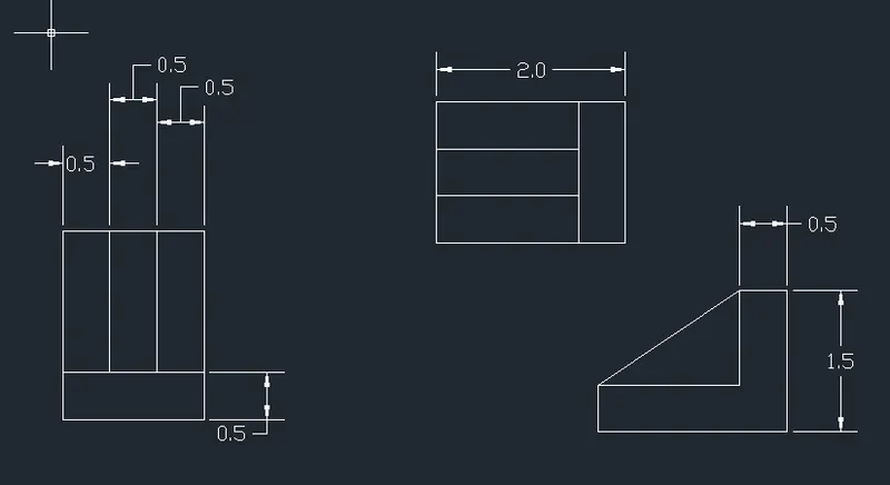
- Draw a rectangle of length 1.5mm and width 2mm by taking rectangle command
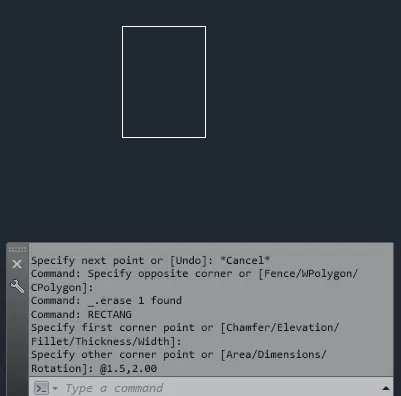
- Draw a line of lenght 0.5mm of equal intervals on the width line
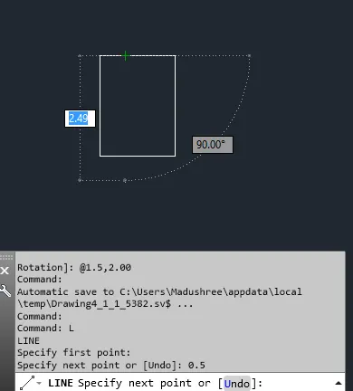
- And also draw a line of length 0.5mm on the length line of rectangle
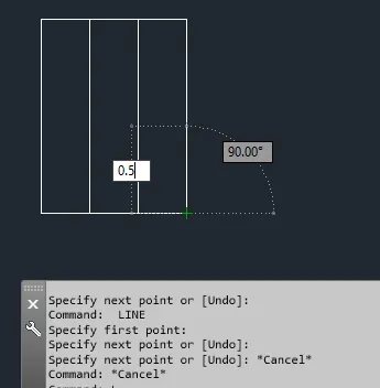
- Trim the unwanted line by using trim tool command
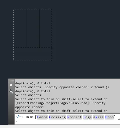
- Select that object and copy to another location
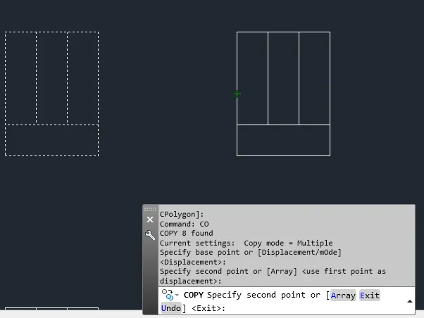
- And rotate the copied object in the anticlockwise direction and give rotational angle as 90degrees
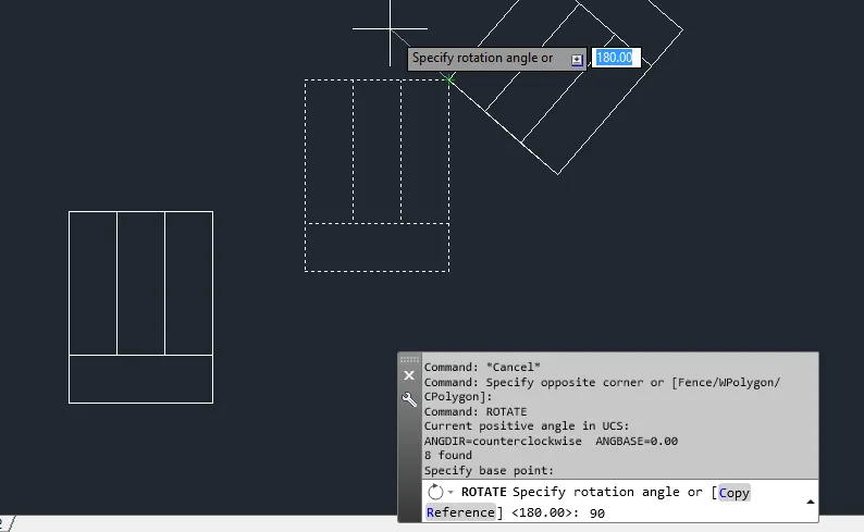
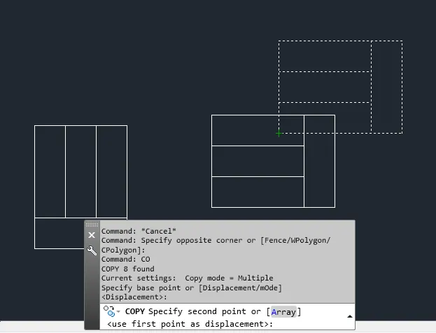
- Again copy the copied object to another location
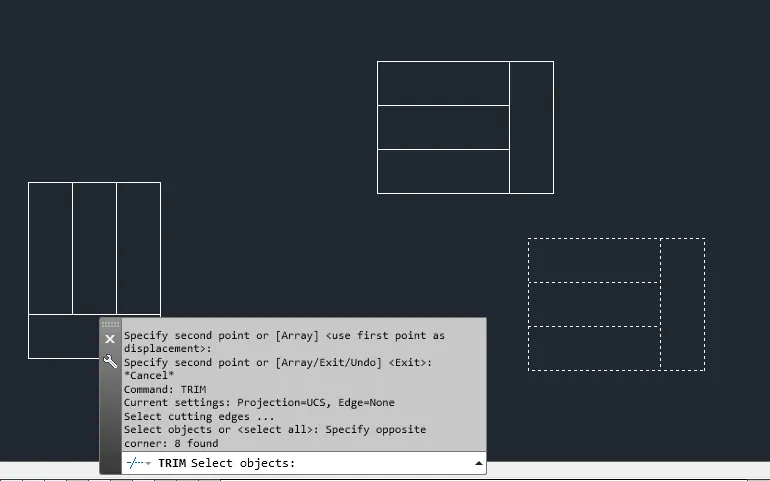
- Trim off the unwanted lines from the object to get the inclined line by using the trim tool
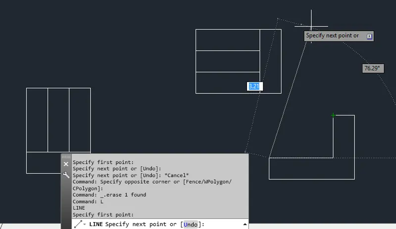
- Join the two points using line tool and measure the distance between the points and between the lines
Result
7)
Step1
- Continue in the same drawing sheet because the units given is decimals unit as same as the previous drawing
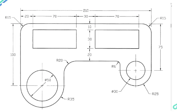
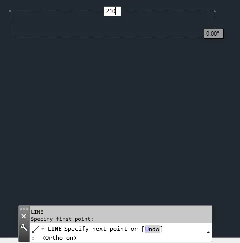
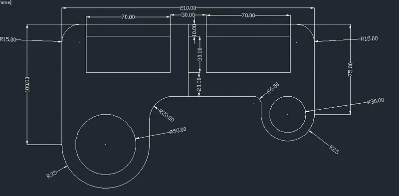
- Draw a line of length 210mm in the horizontal direction
- Draw a another line of length 75mm as a width and of length 100mm on another side
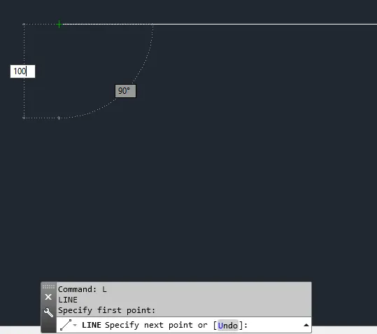
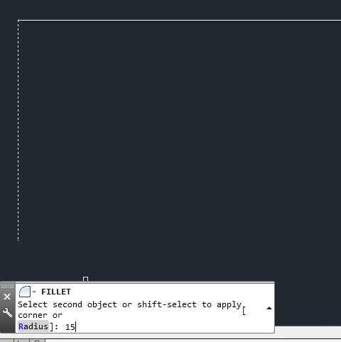
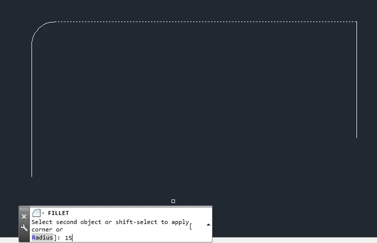
- Fillet the edge of radius 15mm on both the edges by using fillet tool
- Draw a rectangle of length 30mm and width as 70mm below the line of distance of 10mm and place it between 20mm line from the end
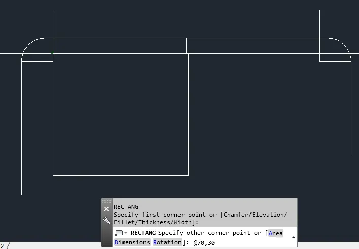
- Now delete the reference lines that we have taken to draw a rectangle
- Take a fillet tool and fillet the lines of radius 35mm
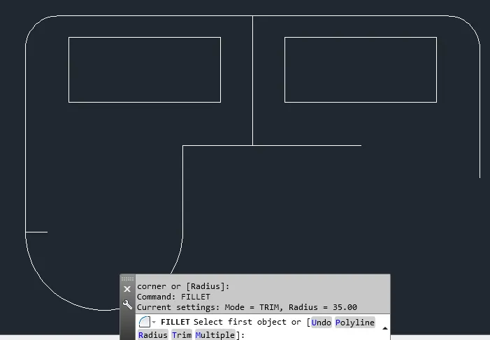
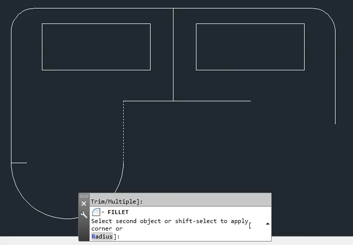
- And again give 20mm fillet radius
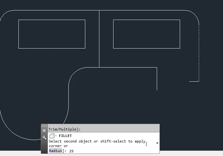
- Again take a fillet of radius 25mm
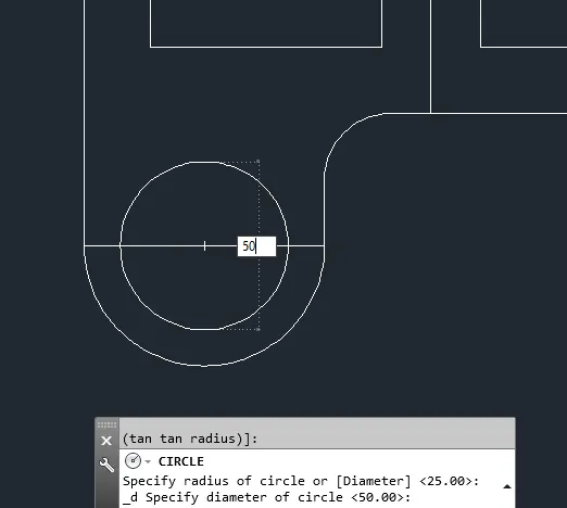
- Draw a circle of diameter 50mm using circle tool with the centre of the fillet arc
- Again draw a circle of radius 30mm on other side with the centre of the fillet arc
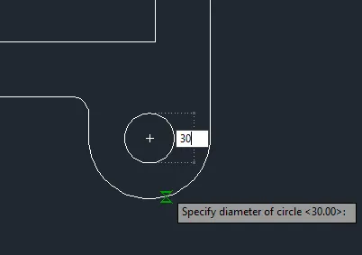
- Finally measure the distance, fillet radius and circle dia with the relevant dimensioning tools
Result
8)
Step1
- Continue in the same drawing as decimal units because last drawing was in decimals as same this drawing
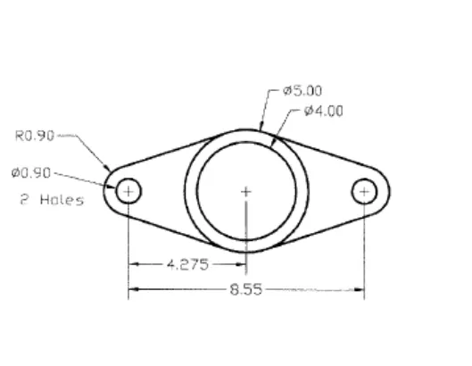
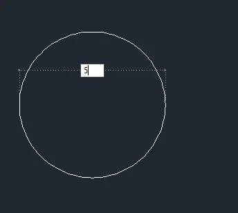
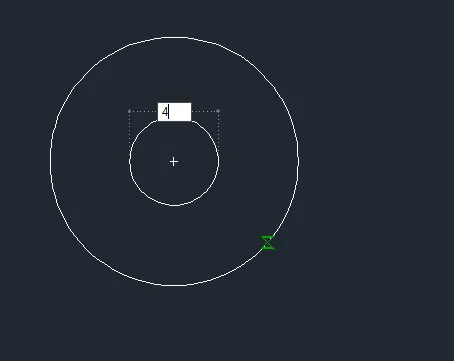
- Draw a circle of diameter 5mm using circle tool, centre diameter option
- Again draw a circle of diameter 4mm inside of a circle which was created earlier
- Again draw a circle of dia 0.9mm which is 4.275mm away from the centre of the 5mm dia circle on both the sides
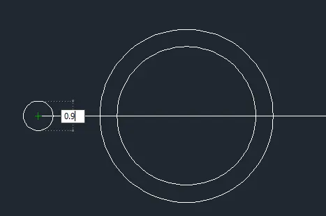
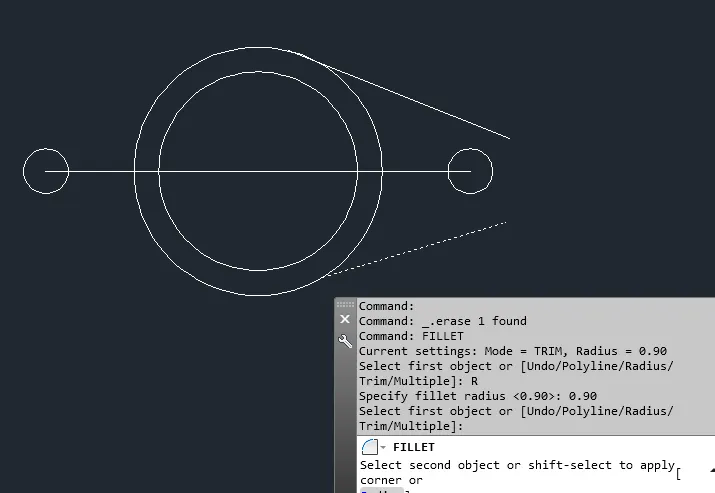
- Draw a tangent to the circle both the sides
- Draw a fillet of radius 0.9 both the sides
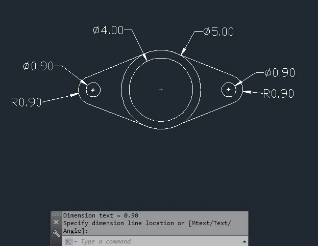
- Finally measure the distance and radius of fillet and diameter using dimension tools
Result
10)
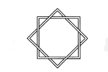
Step1
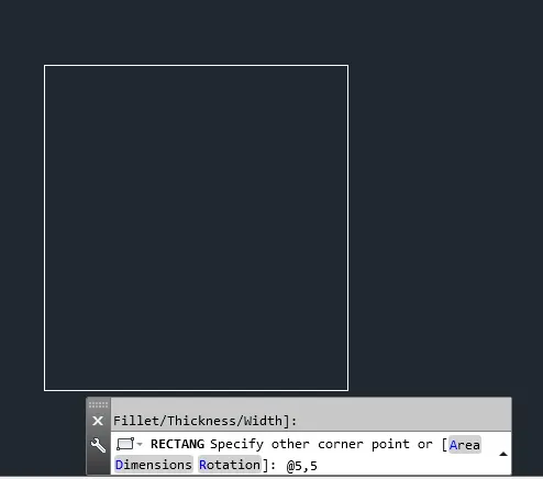
- Create a rectangle of some particular dimension using rectangle tool
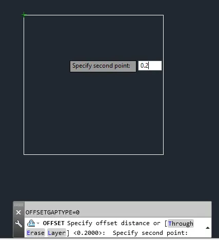
- Take a offset of 0.2mm inside the rectangle of equal sides
- Mirror this object by using mirror tool by not deleting the source object
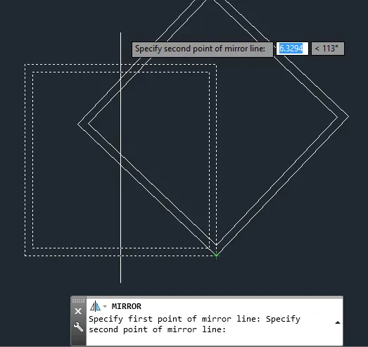
- After mirroring the object place the object to the axis by using move command
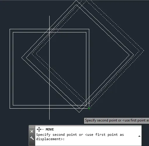
- Trim the unwanted intersected lines by using trim command
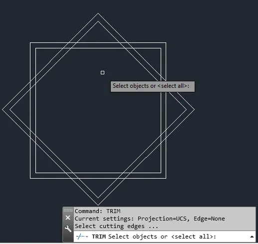
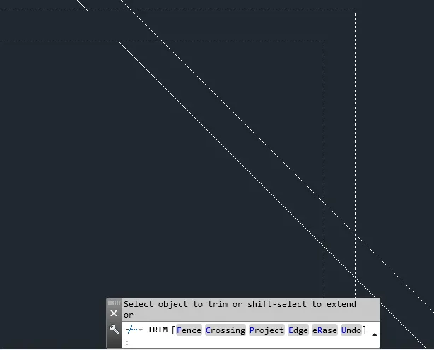
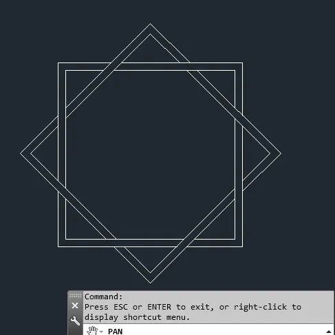
Result
11)
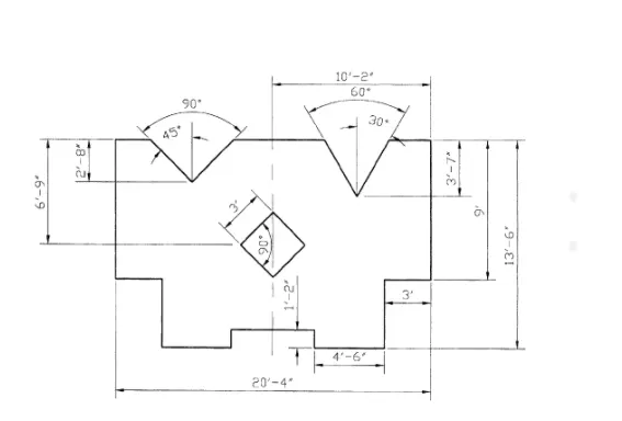
Step1
- Take a new drawing in the application menu new option
- Give startup value 1 and units as engineering precision is 0'0.00" and insertion scale as inches
- Set the units to engineering units precision is 0'0.00"
- Give limits as 500', 500'
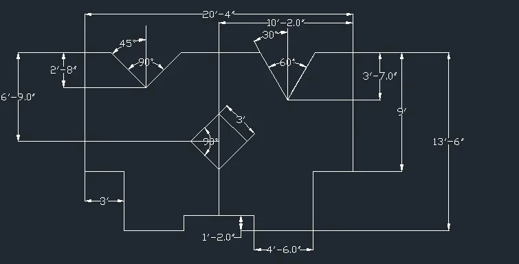
- Draw a line of length 13'6" in vertical axis
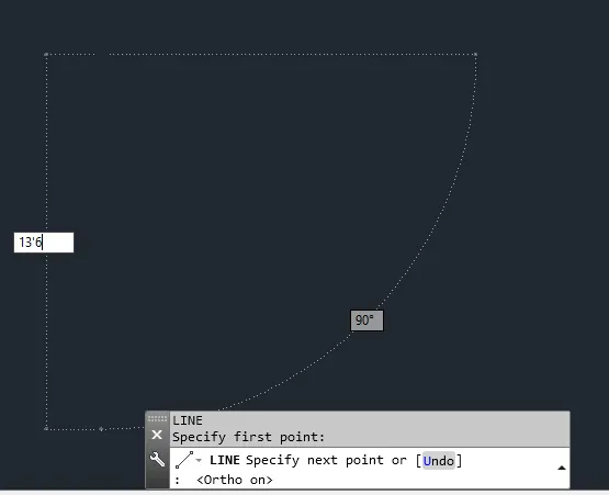
- Take a line of length 3' in the horizontal x axis
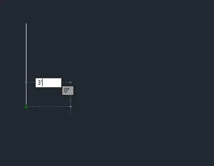
- Draw a line of 4'6" in horizontal axis
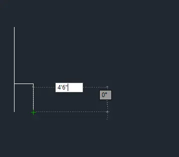
- And 1'2" vertically upwards
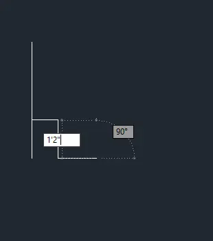
- Again take a line of length 20'4" as a length in the positive x direction
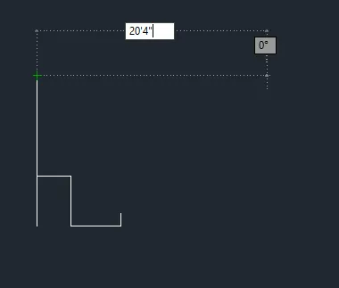
- Again take a line of length 13'6" in negative y direction
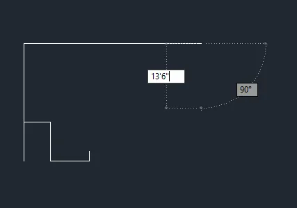
- Mark the 9' distance on the vertical line of length 13'6" line
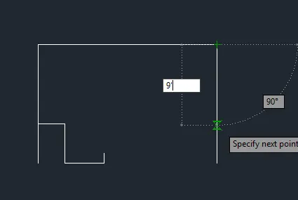
- Again take a line of 3' in negative x axis from the 9' line
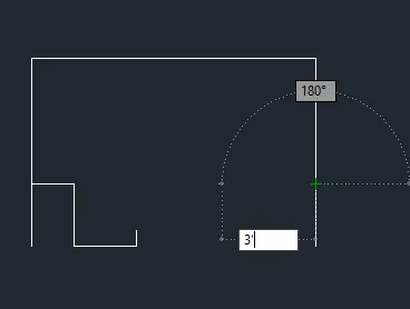
- Take a line to the end of the line and draw a line of length 4'6" in the negative x axis
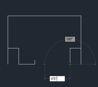
- Again take 1'2" line upwards
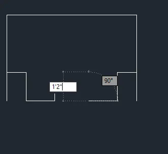
- Finally close the line
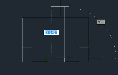
- And the geometry is created
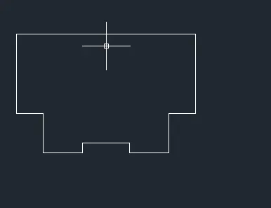
- Next in order to do remaining we have delete the width line of length 20'4"
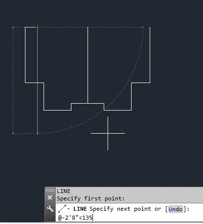
- And take a line and draw using relative coordinate system length and angle method
- Draw a line by relative coordinate system by giving -2'8" as a length in order to get negative direction and 135 degrees angle
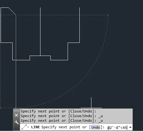
- And again take a relative coordinate method and draw a line of length 2'8" at an angle of 45 degrees
- And again take a line of relative coorcdinate system of length -3'7" at an angle of 120degrees
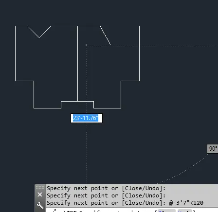
- Again take a line of length 3'7" at an angle of 60degrees
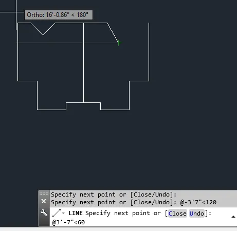
- Finally join the end point
- Create a rectangle of length 3' and width 3' and place it in on the geometry by a distance of 6'9"
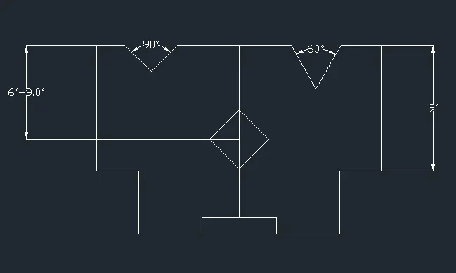
- Finally measure the dimensions by using various dimension tool
Result
9)
Step1
- Go to new drawing in the application menu tab
- Go to starup command give value 1
- Set the units to engineering and precision is 0'0"
- Press ok
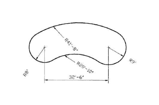
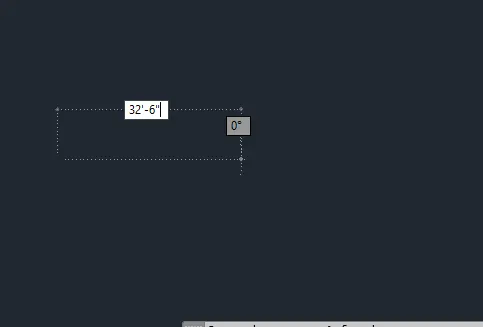
- Go to Line command and draw a line of length 32'-6"
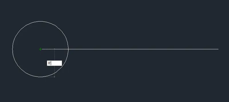
- Go to circle radius and draw a circle of radius 8' at one end of the line
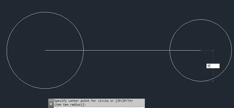
- Draw a circle of radius 9' at the other end of the line
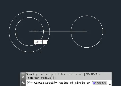
- Draw a another circle of radius 33'-8"
- Draw a another circle of radius 32'8" on another end of a line
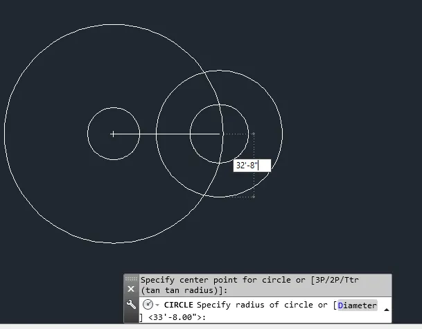
- With the intersection of these two circles at the botton create a circle of radius 41'8"
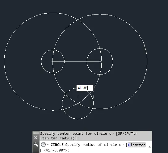
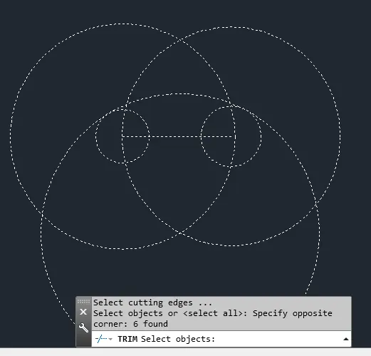
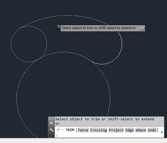
- Trim out the extra arcs of a circle by using trim command
- By using tangent tangent radius option in the circle draw a circle of radius 20'-10" between two circles
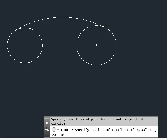
- Finally trim off the unwanted portions from the geometry
- Finally measure the dimensions by using dimension tools
Result